-5-
[Adjustment Condition]
● Input signal
Video signal .......................... 1.0Vp-p/75Ω terminated, 16 steps gray
scale (Composite video signal)
Computer signal .................... 0.7Vp-p/75Ω terminated, 16 steps gray
scale pattern
Component Video signal ...... 0.7Vp-p/75Ω terminated, 16 steps gray
scale (Component video signal with
480p, 575p, 720p or 1080i format)
● Picture control mode .............. “STANDARD” mode unless otherwise
noted.
Note:
* Please refer to “Service Adjustment Menu Operation” for entering the service mode and adjusting the service
data.
● Circuit Adjustments
CAUTION: The each circuit has been made by the fine adjustment at factory. Do not attempt to adjust the follow-
ing adjustments except requiring the readjustments in servicing otherwise it may cause loss of per-
formance and product safety.
Electrical Adjustments
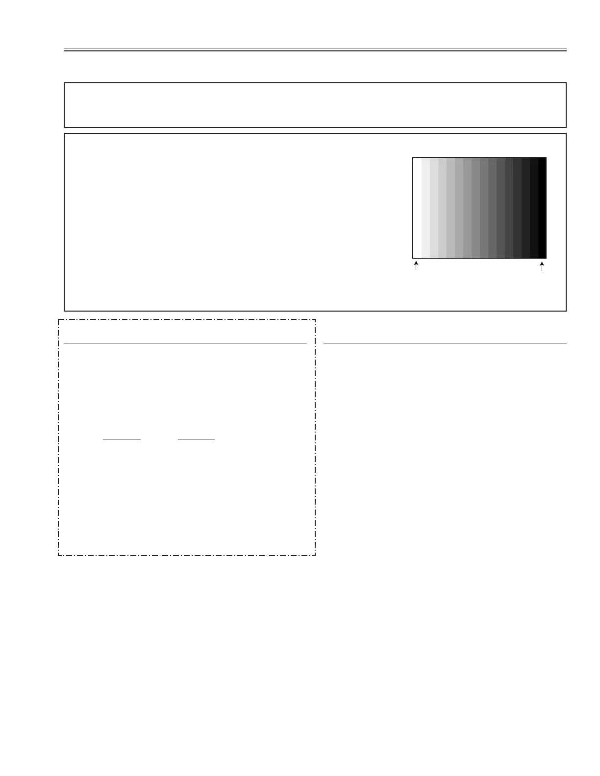
16 steps gray scale pattern
After replacing the Power Board readjust the Output
voltage adjustment as follows.
1. Connect a digital voltmeter to pins 1 (+) and 3 (-) of
K6D.
2. Adjust the voltage by using VR611 as following.
AC Input Reading
230V 380V ±2V
Caution:
Be sure to connect the lamp when taking this adjust-
ment.
Output Voltage adjustment
1. Set the lamp mode to "Normal" and then enter the
service mode.
2. Select group no. “111”, item no. “5” and set data value
to “1”.
3. Connect a digital voltmeter to test point “TP12V1”(+)
and chassis ground (-). Select item no. “89”and
change data value to adjust voltage to be 6.5 ±0.1V.
4. Connect a digital voltmeter to test point “TP12V2”
(+) and chassis ground (-). Select item no. “91”and
change data value to adjust voltage to be 6.5 ±0.1V.
5. Connect a digital voltmeter to test point “TP12V1”(+)
and chassis ground (-). Select item no. “90”and
change data value to adjust voltage to be 13.5 ±0.1V.
6. Connect a digital voltmeter to test point “TP12V2”(+)
and chassis ground (-). Select item no. “92”and
change data value to adjust voltage to be 13.5 ±0.1V.
7. Select item no. “5” and set data value to “0”.
z Fan Control adjustment
* This adjustment is not required even if the power
board is replaced because this adjustment is carried
out before parts shipment.
 Loading...