-8-
Electrical Adjustments
1. Receive the 1 line black/white pattern computer sig-
nal with Computer2 [RGB] mode.
2. Enter the service mode.
3. Project only green light component to the screen.
4. Select group no. “10”, item no. “9”and change data
value to obtain the minimum flicker on the screen.
5. Project only red light component to the screen.
6. Select item no. “10” and change data value to obtain
the minimum flicker on the screen.
7. Project only blue light component to the screen.
8. Select item no. “11 and change data value to obtain
the minimum flicker on the screen.
⁄0 Common Center adjustment
[PC WHITE BALANCE ADJUSTMENT]
1. Receive the 16-step gray scale computer signal with
Computer2 [RGB] mode.
2. Enter the service mode, select group no. “9” item no.
“11” (Red) or “12” (Blue), and change Data values
respectively to make a proper white balance.
[AV WHITE BALANCE ADJUSTMENT]
1. Receive the 16-step gray scale composite video sig-
nal with Video [Video] mode.
2. Enter the service mode, select group no. “9” item no.
“11” (Red) or “12” (Blue), and change Data values
respectively to make a proper white balance.
Confirm that the same white balance is obtained in
video and computer input.
⁄2 White Balance adjustment
If you find the color shading on the screen, please
adjust the white uniformity by using the proper comput-
er and “Color Shading Correction” software supplied
separately.
The software can be ordered as follows;
COLOR SHADING CORRECTION ver. 3.0
Ser
vice Parts No. 645 056 6288
[PC-GAMMA ADJUSTMENT]
1. Receive the 16-step grey scale computer signal with
Computer2 [RGB] mode.
2. Enter the service mode.
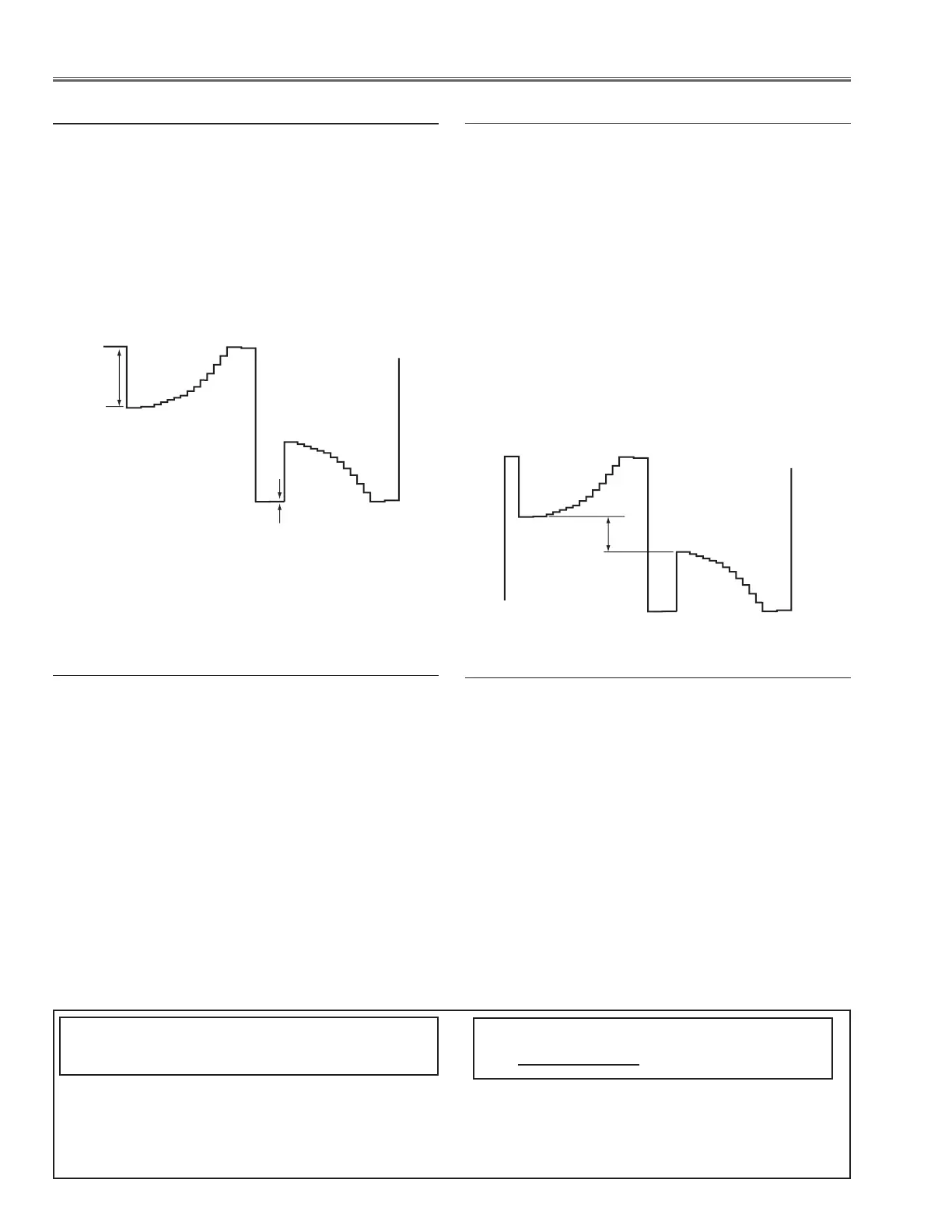
3. Connect an oscilloscope to test point “TPG1”(+)
and chassis ground (-).
4. Select group no. “9”, item no. “10” and change data
value to adjust amplitude “a” to be 2.0 ±0.1V.
[AV-GAMMA ADJUSTMENT]
1. Receive the 16-step grey scale video signal with
Video [Video] mode.
2. Enter the service mode.
3. Connect an oscilloscope to test point “TPG1”(+)
and chassis ground (-).
4. Select group no. “9”, item no. “10” and change data
value to adjust amplitude “a” to be 1.3 ±0.1V.
 Loading...