-7-
Electrical Adjustments
1. Receive the 16-step grey scale computer signal with
Computer2 [RGB] mode.
2. Enter the service mode
3. Connect a digital voltmeter to test point “TPGV1”(+)
and chassis ground (-).
4. Select group no. “10”, item no. “0” and change data
value to adjust the voltage to be 7.0 ±0.05V.
5. Connect a digital voltmeter to test point “TPRV1”(+)
and chassis ground (-).
6. Select item no. “1” and change data value to adjust
the voltage to be 7.0 ±0.05V.
7. Connect a digital voltmeter to test point “TPBV1”(+)
and chassis ground (-).
8. Select item no. “2” and change data value to adjust
the voltage to be
7.0 ±0.05V.
9. Connect a digital voltmeter to test point “TPGV2”(+)
and chassis ground (-).
10. Select item no. “6” and change data value to adjust
the voltage to be 8.0 ±0.05V.
11. Connect a digital voltmeter to test point “TPRV2”(+)
and chassis ground (-).
12. Select item no. “7” and change data value to adjust
the voltage to be 8.0 ±0.05V.
13. Connect a digital voltmeter to test point “TPBV2”(+)
and chassis ground (-).
14. Select item no. “8” and change data value to adjust
the voltage to be 8.0 ±0.05V.
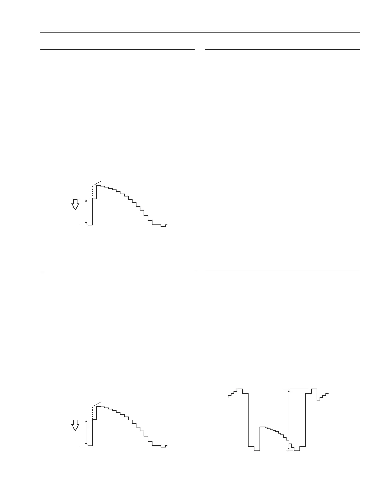
m Video Center adjustment
1. Receive the 16-step grey scale composite video sig-
nal with Video [Video] mode.
2. Enter the service mode.
3. Connect an oscilloscope to test point “TPG1”(+)
and chassis ground (-).
4. Select group no. “9”, item no. “1” and adjust the ampli-
tude “a” to be minimum by changing the Data value.
5. Connect an oscilloscope to test point “TPR1” (+) and
chassis ground (-).
6. Select item no. “2” and adjust the amplitude “a” to be
minimum by changing the Data value.
7. Connect an oscilloscope to test point “TPB1” (+) and
chassis ground (-).
8. Select item no. “3” and adjust the amplitude “a” to be
minimum by changing the Data value.
n Sub Gain adjustment [Video]
1. Receive the 16-step grey scale computer signal with
Computer2 [RGB] mode.
2. Enter the service mode.
3. Connect an oscilloscope to test point “TPG1”(+)
and chassis ground (-).
4. Select group no. “9”, item no. “1” and adjust the ampli-
tude “a” to be
minimum by changing the Data value.
5. Connect an oscilloscope to test point “
TPR1” (+) and
chassis ground (-).
6. Select item no. “2” and adjust the amplitude “a” to be
minimum
by changing the Data value.
7. Connect an oscilloscope to test point “
TPB1” (+) and
chassis ground (-).
8. Select item no. “3” and adjust the amplitude “a” to be
minimum by changing the Data value.
b Sub Gain adjustment [PC]
1. Receive the 16-step grey scale computer signal with
Computer2 [RGB] mode.
2. Enter the service mode.
3. Connect an oscilloscope to test point “TPG1” (+)
and chassis ground (-).
4. Select group no. “10”, item no. “3” and change data
value to adjust amplitude “a” to be 10.0 ±0.1V.
5. Connect an oscilloscope to test point “TPR1” (+) and
chassis ground (-).
6. Select item no. “4” and change data value to adjust
amplitude “a” to be 10.0 ±0.1V.
7. Connect an oscilloscope to test point “TPB1” (+) and
chassis ground (-).
8. Select item no. “5” and change data value to adjust
amplitude “a” to be 10.0 ±0.1V.
 Loading...