-25-
[Adjustment Condition]
● Input signal
Video signal ......................... 1.0Vp-p/75Ω terminated, 16 steps gray
scale (Composite video signal)
Computer signal .................... 0.7Vp-p/75Ω terminated, 16 steps gray
scale pattern
Component Video signal ....... 0.7Vp-p/75Ω terminated, 16 steps gray
scale (Component video signal with
480p, 575p, 720p or 1080i format)
● Picture control mode .............. “STANDARD” mode unless otherwise
noted.
Note:
* Please refer to “Service Adjustment Menu Operation” for entering the service mode and adjusting the service
data.
Circuit Adjustments
CAUTION: The each circuit has been made by the fine adjustment at factory. Do not attempt to adjust the follow-
ing adjustments except requiring the readjustments in servicing otherwise it may cause loss of perfor-
mance and product safety.
Electrical Adjustments
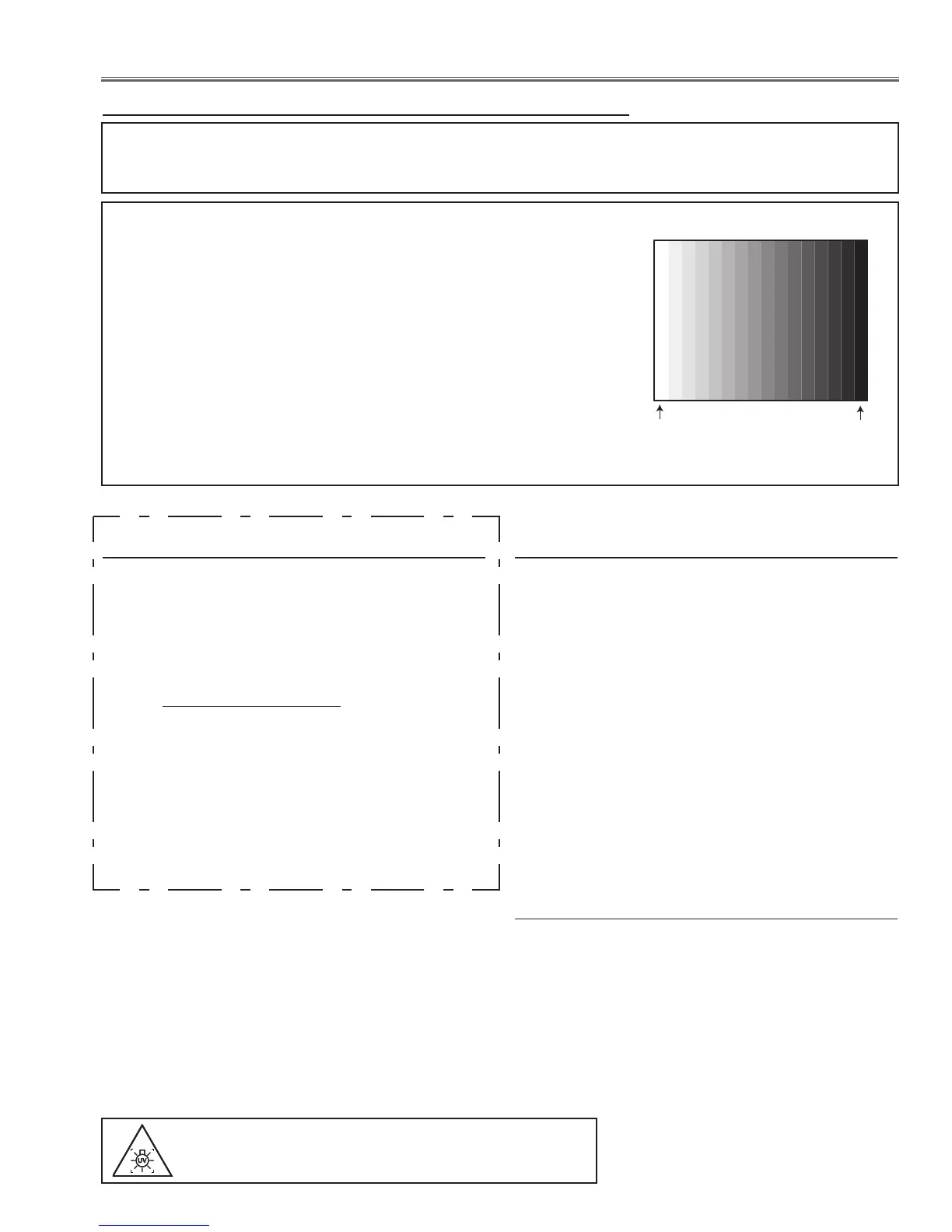
16 steps gray scale pattern
After replacing the Power Board readjust the Output
voltage adjustment as follows.
1. Connect a digital voltmeter to pins 1 (+) and 3 (-) of
K6D.
2. Adjust the voltage by using VR611 as following.
AC Input Reading
230V 380V ±2V
Caution:
Be sure to connect the lamp when taking this adjust-
ment.
Output Voltage adjustment
* This adjustment is not required even if the power
board is replaced because this adjustment is carried
out before parts shipment.
WARNING : USE UV RADIATION EYE AND SKIN
PROTECTION DURING SERVICEING
1. Set the lamp mode to "Normal" and then enter the
service mode.
2. Connect a digital voltmeter to test point “TPFANA” (+)
and chassis ground (-). Select group no. “111”, item
no. “94” and change data value to adjust voltage to
be 5.2 ±0.1V.
3. Connect a digital voltmeter to test point “TPFANB”
(+) and chassis ground (-). Select item no. “96” and
change data value to adjust voltage to be 5.2 ±0.1V.
x Fan Control adjustment
WARNING : USE UV RADIATION EYE AND SKIN
PROTECTION DURING SERVICEING
1. Enter the service mode.
2. Panel Type Check
Select group no. “
290”, item no. “0”. Check the data
value as follows;
Data value: 0 For L-Type of LCD Panel
Data value: 20 For R-Type of LCD panel
3. Panel Type Setting
Select group no. “
290”, item no. “1” and change data
value from 10 to 0 or 20 depending on your LCD
Panel type. When the data value reaches 0 or 20,
it returns to 10 quickly. The gamma-characteristics
changes according to your selection.
* Refer to the item "LCD Panel/Prism Ass'y removal"
for the panel type check.
z Panel Type Check and Setting

 Loading...


