-21-
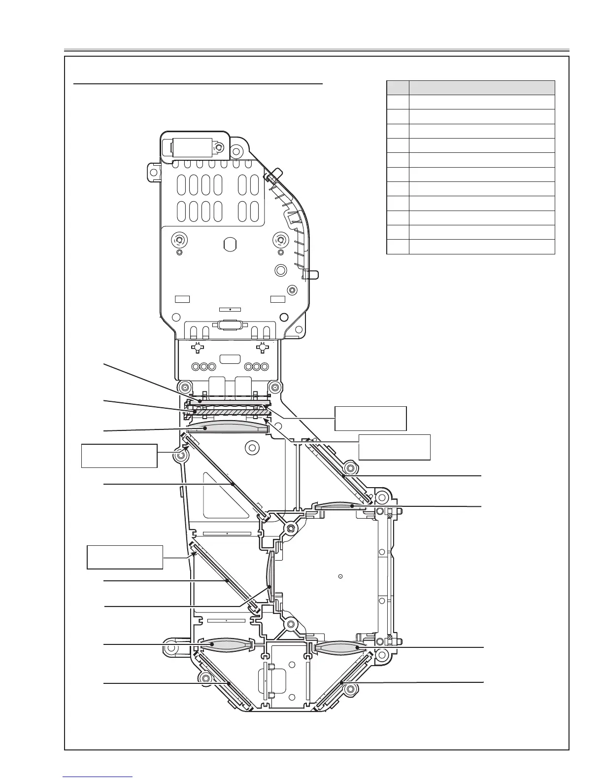
Optical Parts Disassembly
5
9
Fig.8
1
6
10
When mounting or assembling the optical parts in the opti-
cal unit, the parts must be mounted in the specified loca-
tion and direction as shown in figure below.
2
3
4
8
8
11
, Locations and Directions
Rugged surface is
facing this side.
Point marker is printed
on this side up
Point marker is printed
on this side up
No. Parts Name
1 Integrator lens (OUT)
2 Prism beam splitter (PBS)
3 Condenser lens (OUT)
4 Dichroic mirror (B)
5 Dichroic mirror (G)
6 Condenser lens (G)
7 Relay Lens (IN)
8 Mirror (R)
9 Condenser lens (R)
10 Condenser lens (B)
11 Mirror (B)
7
Film attached side is
facing this side.

 Loading...