-15-
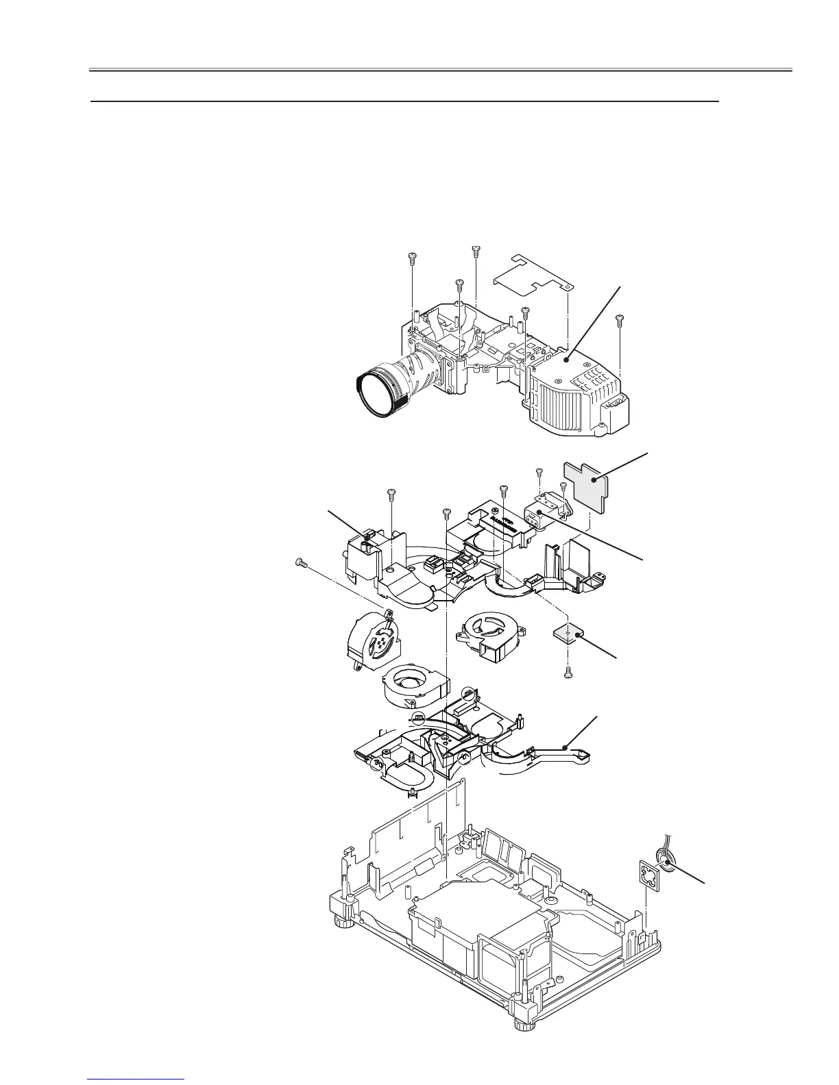
Mechanical Disassembly
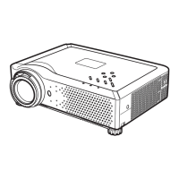
v Optical unit, Temp., Line Filter board, Fans and Speaker removal
Fig.4
Temp. board
SP901
Noise filter
Optical unit
E (T3x6)x2
B (T3x8)
F (T3x6)
Line filter board
FN904
FN907
FN905
Duct bottom
1. Remove 5 screws A(T3x5) to remove the the Optical unit.
2. Remove 3 screws B (T3x8) and 4 hooks on the duct to remove
the Duct. top and bottom.
3. Remove screw C(T3x8) to remove the fan(FN904).
4. Remove 2 screws E(T3x6) and screw F(T3x6) to remove the Line filter
board and Temp. board.
5. Remove fans (FN905, FN907) and speaker (SP901).
Duct top
A(T3x8)x5
A
A
A
A
E
B
B
Hook
Hook
Hook
Hook
C (T3x8)
 Loading...