25
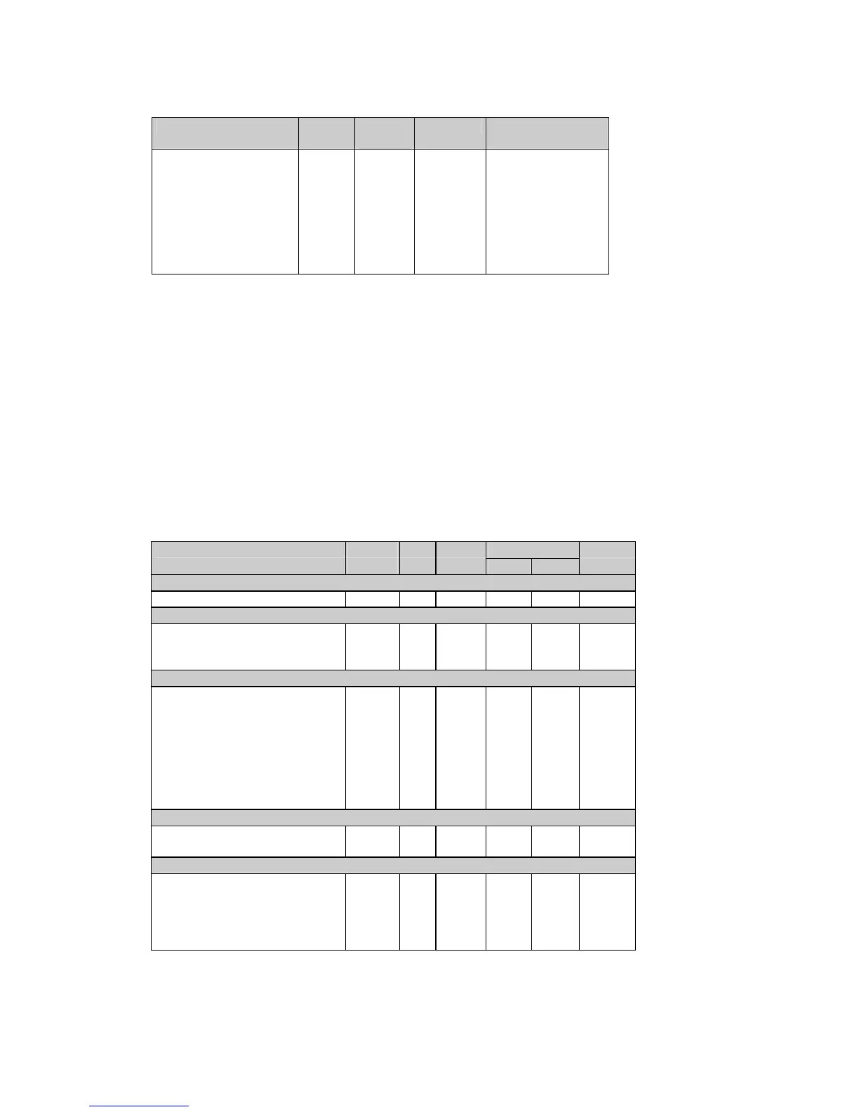
Table 5-17 Setpoint Setup Registers
Parameter Offset Size,
byte
Direction Range
Trigger parameter ID +0 2 R/W see Table 5-18
Action +1 2 R/W see Table 5-19
Operate delay +2 2 R/W
0-9999 (× 0.1 sec)
Release delay +3 2 R/W
0-9999 (
×
0.1 sec)
Operate limit +4
+5
4 R/W see Table 5-18
Release limit +6
+7
4 R/W see Table 5-18
The setpoint is disabled when its trigger parameter is set to NONE. To disable the setpoint,
write zero into this register.
When writing the setpoint registers (except the event when the setpoint is to be disabled), it is
recommended to write all the setpoint registers using a single request, or disable the setpoint
before writing into separate registers. Each value being written is checked for compatibility with
the other setpoint parameters; if the new value does not conform to these, the request will be
rejected.
Operate and release limits for the trigger parameters and their conversion scales are indicated
in Table 5-18. Each limit value occupies two contiguous registers, the first of which (low word)
contains the limit value, and the second (high word) is reserved for long parameters. This
register is always read as zero. When written, its value is ignored.
Limits indicated in Table 5-18 by a N/A mark are read as zeros. When writing, they can be
omitted or should be written as zeros.
When a setpoint action is directed to a relay allocated to output energy pulses, an attempt to re-
allocate it for a setpoint will result in a negative response.
Table 5-18 Setpoint Trigger Parameters
Trigger parameter Trigger Size, Unit
Limit/scale
c
Con-
ID byte Low High version
None
None 0 2 N/A N/A NONE
Phase reversal
Positive phase rotation reversal 35073 2 N/A N/A NONE
Negative phase rotation
reversal
35074 2 N/A N/A NONE
High/low real-time values on any phase
High voltage
f
3584 2 V 0 Vmax LIN3
Low voltage
f
36096 2 V 0 Vmax LIN3
High current 3585 2 A 0 Imax LIN3
Low current 36097 2 A 0 Imax LIN3
Reserved 3591 2
Reserved 3592 2
Reserved 3593 2
Reserved 3594 2
High/low real-time auxiliary values
High frequency
e
4098 2 0.01Hz 0 100.00 LIN3
Low frequency
e
36866 2 0.01Hz 0 100.00 LIN3
High/low average values per phase
High current L1 4355 2 A 0 Imax LIN3
High current L2 4356 2 A 0 Imax LIN3
High current L3 4357 2 A 0 Imax LIN3
Low current L1 37123 2 A 0 Imax LIN3
Low current L2 37124 2 A 0 Imax LIN3