25
2.5.5 Powermeter Status Table
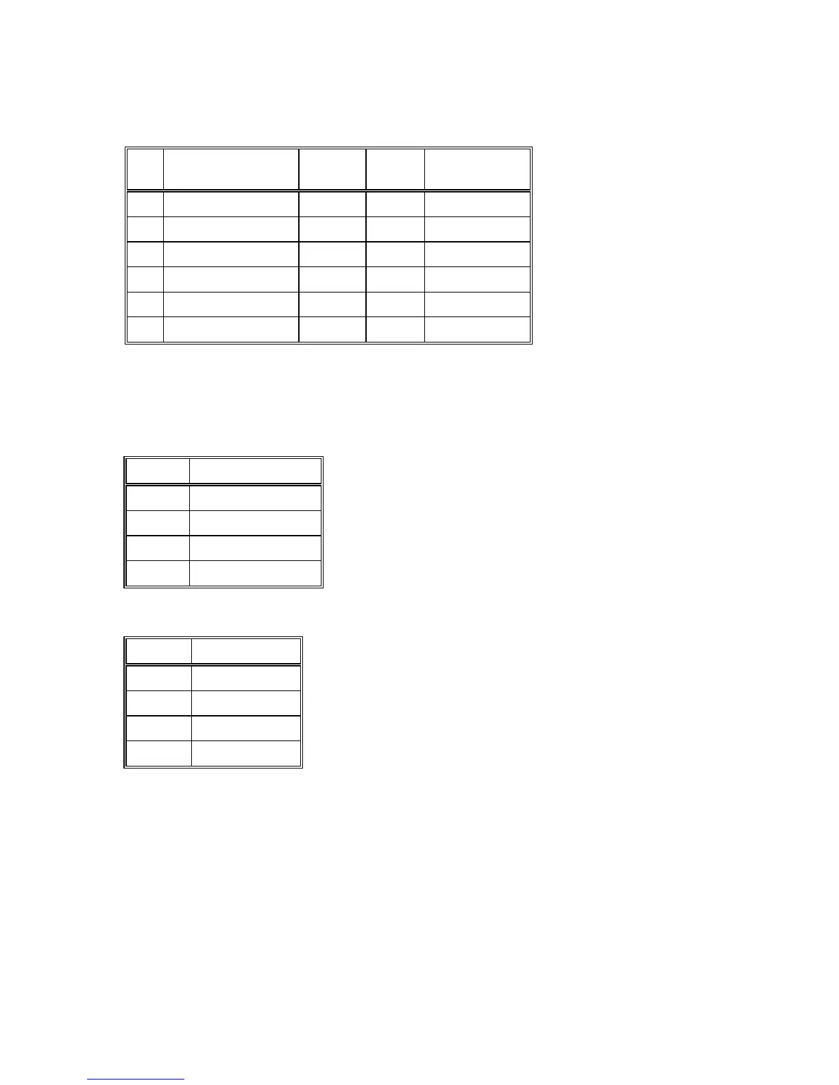
Powermeter Internal Table #10
No Parameter Address No. of
Bytes
Range
1 State Flags 0 2 0 - 255
2 Keypad Status 1 2 0 - 15
3 Relay Status 2 2 0 - 15
4 DIP Switch 1 and 2 3 2 0 to 65535
5 Dry contacts status 4 2 0 to 255
6 Version Number 5 2 0 to 65000
Normal state of State Flags is 0. Writing 65535 to State Flags will cause the Powermeter to
restart.
Status of the front panel keypad keys:
Bit No. Key
0 × (Up Arrow)
1 RESET
2 SELECT
3 Ø (Down Arrow)
Status of the relays:
Bit No. Relay No.
0 4
1 3
2 2
3 1
('1' = closed, '0' = open)

 Loading...


