24
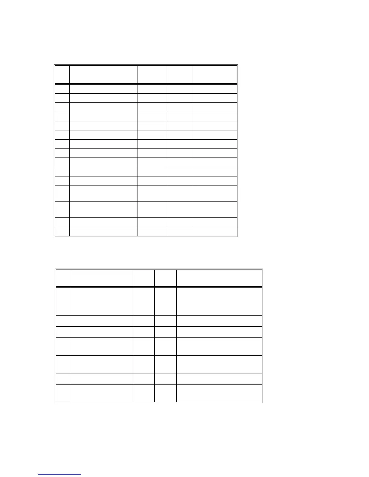
Analog Output Setpoint Table
Powermeter Internal Table #8
No Setpoint Address No. of
bytes
Range
1 Voltage - A 0 2 0 to 14 or c
2 Voltage - B 1 2 0 to 14 or c
3 Voltage - C 2 2 0 to 14 or c
4 Current - A 3 2 0 to 14 or c
5 Current - B 4 2 0 to 14 or c
6 Current - C 5 2 0 to 14 or c
7 Reserved 6 2
8 Reserved 7 2
9 Active Power 8 2 0 to 14 or c
10 Reactive Power 9 2 0 to 14 or c
11 Apparent Power 10 2 0 to 14 or c
12 Accumulated
Maximum Demand
11 2 0 to 14 or c
13 Accumulated Apparent
Maximum Demand
12 2 0 to 14 or c
14 Power Factor 13 2 0 to 14 or c
15 Frequency 14 2 0 to 14 or c
c 65535 to suppress
2.5.4 System Configuration Setpoint
Powermeter Internal Table #9
No Setpoint Addr No. of
bytes
Range
1
Wiring Configuration 0 2 0 = 3-wire direct connection
1 = 4-wire line to neutral
2 = 3-wire open delta
3 = 4-wire line to line
2
PT Ratio c 1 2 1 to 65000
3
CT Primary Current 2 2 1 to 50000
4
Maximum Demand
Period
3 2 1,2,5,10,20,30,60 or
255=External synchronization
5
Ampere Maximum
Demand Period
4 2 1 to 1800
6
Buffer Size 5 2 8 or 32 ('nor' or 'UnSt')
7
Reset Mode 6 2 0 Enable
1 Disable
c For PT ratio multiply desired value by ten (10).

 Loading...


