23
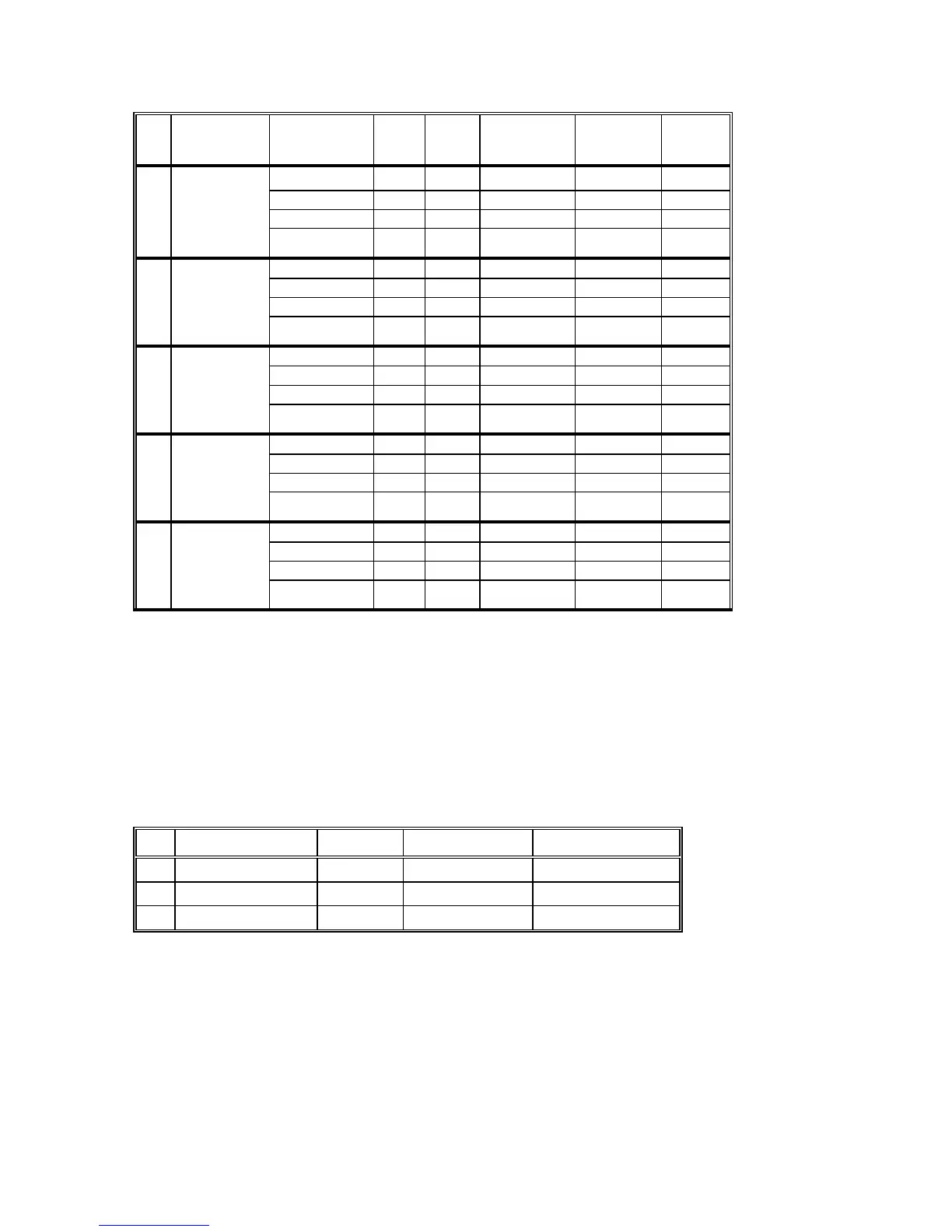
Setpoint Data type Add-
ress
No. of
Bytes
Data
Conversion
Type
HI
Scale
LO
Scale
4
High High Bound 12 2 LIN3 Imax 0
Unbalanced High Delay 13 2 None 999 or c 0
Current Low Bound 14 2 Line3 Imax 0
Low Delay 15 2 None 999 or c 0
5
Maximum High Bound 16 2 LIN3 Pmax -Pmax
Demand High Delay 17 2 None 999 or c 0
Low Bound 18 2 Line3 Pmax -Pmax
Low Delay 19 2 None 999 or c 0
6
High High Bound 20 2 LIN3 Pmax -Pmax
Reactive High Delay 21 2 None 999 or c 0
Power Low Bound 22 2 Line3 Pmax -Pmax
Low Delay 23 2 None 999 or c 0
7
High High Bound 24 2 LIN3 Pmax -Pmax
Apparent High Delay 25 2 None 999 or c 0
Power Low Bound 26 2 Line3 Pmax -Pmax
Low Delay 27 2 None 999 or c 0
8
Low High Bound 28 2 LIN3 Pmax -1.00
Power High Delay 29 2 None 999 or c 0
Factor Low Bound 30 2 Line3 Pmax -1.00
Low Delay 31 2 None 999 or c 0
c 65535 to suppress
NOTE
Although LO Scale in some setpoints are negative the boundaries must be positive.
A High Delay value of 999 corresponds to a delay of 99.9 seconds.
A Low Delay value of 999 corresponds to a delay of 999 seconds.
The setpoint will be suppressed while the High Delay is suppressed.
Pulsing Setpoints
Powermeter Internal Table #7
No SETPOINT ADDRESS NO OF BYTES RANGE
1
Pulsing kWH 0 2 1 to 200 or c
2
Pulsing -kWH 1 2 1 to 200 or c
3
Pulsing kVARH 2 2 1 to 200 or c
c 65535 to suppress pulsing

 Loading...


