21
2.5.3 Setpoint Tables
Table of Available Setpoints
The following table contains bit flags of available setpoints for the relay.
Bit meaning :
1 Set point exists
0 Set point does not exist
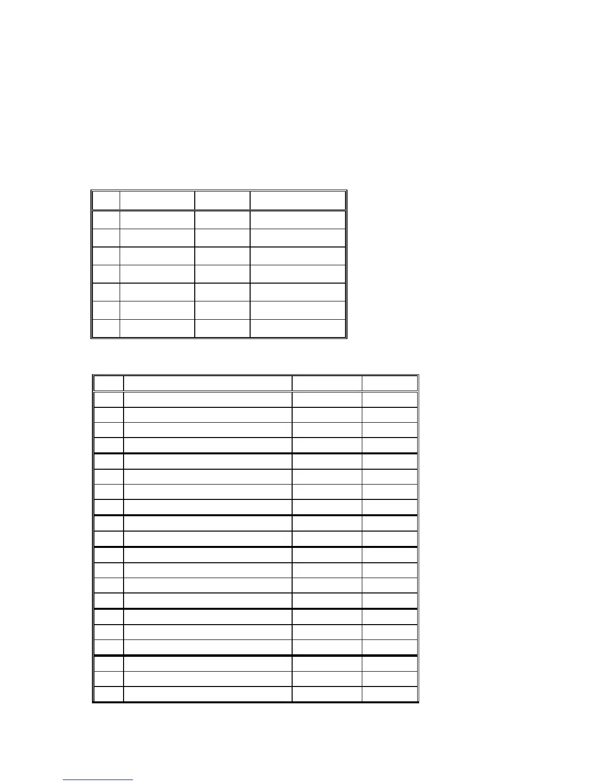
Powermeter Internal Table #2
No. Setpoints Address Number of bytes
1 Relay 1 0 2
2 Relay 2 1 2
3 Relay 3 2 2
4 Relay 4 3 2
5 Analog Output 4 2
6 Pulsing 5 2
7 Configuration 6 2
Format of Available Setpoints for Internal Table #2
No. Setpoint Bit Number Range
1-4 High Voltage 1 0 or 1
1-4 Low Voltage 2 0 or 1
1-4 High Current 3 0 or 1
1-4 High Unbalanced Current 4 0 or 1
1-4 Max Demand 5 0 or 1
1-4 High Reactive Power 6 0 or 1
1-4 High Apparent Power 7 0 or 1
1-4 Low PF. 8 0 or 1
1-4 Reserved 9 0 or 1
1-4 Reserved 10 0 or 1
5 Pulsing kWH 1 0 or 1
5 Pulsing -kWH 2 0 or 1
5 Pulsing kVARH 3 0 or 1
5 Reserved 4 0 or 1
6 Voltage - A 1 0 or 1
6 Voltage - B 2 0 or 1
6 Voltage - C 3 0 or 1
6 Current - A 4 0 or 1
6 Current - B 5 0 or 1
6 Current - C 6 0 or 1

 Loading...


