22
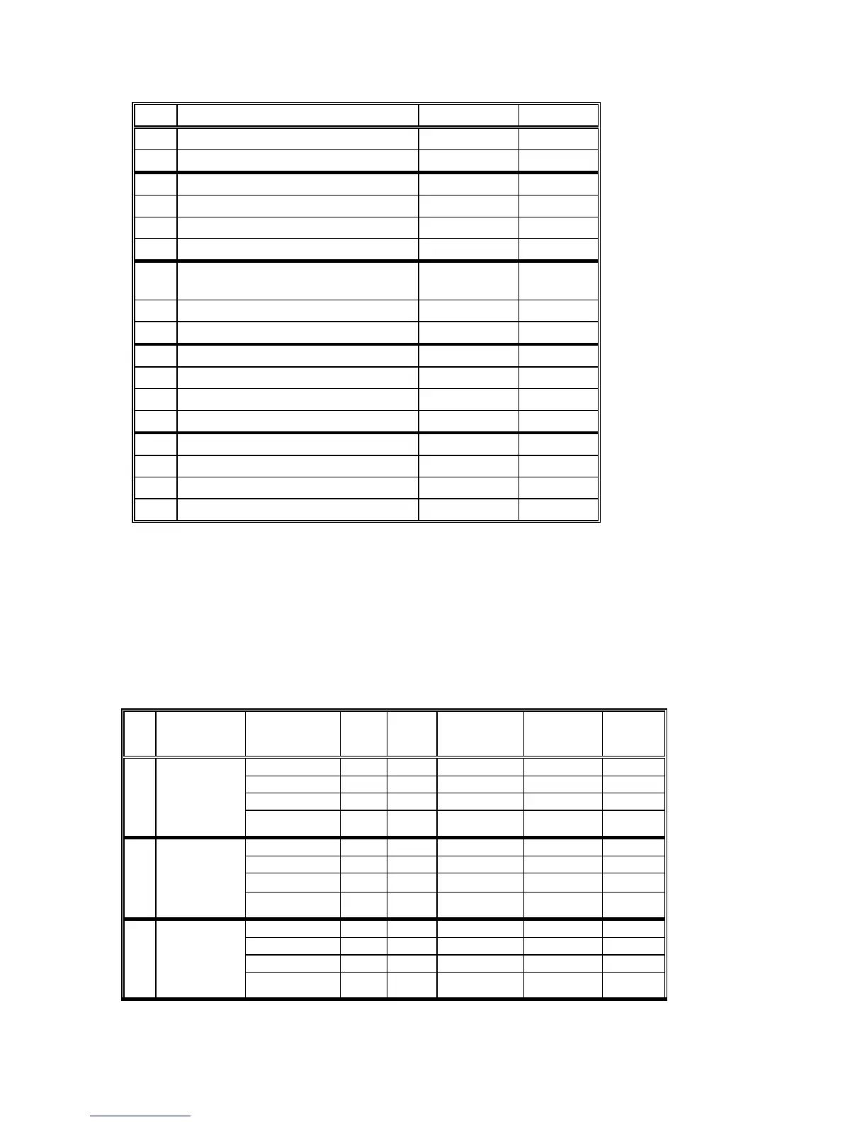
No. Setpoint Bit Number Range
6 Reserved 7 0 or 1
6 Reserved 8 0 or 1
6 Active Power 9 0 or 1
6 Reactive Power 10 0 or 1
6 Apparent Power 11 0 or 1
6 Accumulated Maximum Demand 12 0 or 1
6 Accumulated Apparent Maximum
Demand
13 0 or 1
6 Power Factor 14 0 or 1
6 Frequency 15 0 or 1
7 Wiring Configuration 1 0 or 1
7 PT Ratio 2 0 or 1
7 CT Primary Current 3 0 or 1
7 Maximum Demand Period 4 0 or 1
7 Ampere Maximum Demand Period 5 0 or 1
7 Buffer Size 6 0 or 1
7 Reset Enable/Disable 7 0 or 1
7 Reserved 8 0 or 1
Relay Setpoint Tables
Setpoints for Relay 1 - Table Number 3
Setpoints for Relay 2 - Table Number 4
Setpoints for Relay 3 - Table Number 5
Setpoints for Relay 4 - Table Number 6
Powermeter Internal Tables 3 to 6
Setpoint Data type Add-
ress
No. of
Bytes
Data
Conversion
Type
HI
Scale
LO
Scale
1
High High Bound 0 2 LIN3 Vmax 0
Voltage High Delay 1 2 None 999 or c 0
Low Bound 2 2 Line3 Vmax 0
Low Delay 3 2 None 999 or c 0
2
Low High Bound 4 2 LIN3 Vmax 0
Voltage High Delay 5 2 None 999 or c 0
Low Bound 6 2 Line3 Vmax 0
Low Delay 7 2 None 999 or c 0
3
High High Bound 8 2 LIN3 Imax 0
Current High Delay 9 2 None 999 or c 0
Low Bound 10 2 Line3 Imax 0
Low Delay 11 2 None 999 or c 0

 Loading...


