SATEL VERSA 27
3.19.2
The fu f the system outputs as well as
devices connected to them.
t 12 outputs.
Output test
nction makes it possible to check proper functioning o
You can always tes
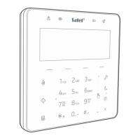
1. Enter the user menu and press in turn . The keypad indicates the
output status by means of LEDs numbered from 1 to 12 (LED OFF – the output is
deactivated; LED ON – the output is activated). The blinking LED means that the cursor is
there. The and keys allow you to move the cursor.
2. Press to activate the output, or press to deactivate the output.
3. Press
to terminate the function.
3.19.3 Checking the leve
The function allows you to ch
l / quality of radio signal
eck:
wire s detectors (if the
nected to the control panel),
wire s devices (if the
the quality of radio signal received by the controller from 433 MHz les
VERSA-MCU controller is con
the level of radio signal received by the controller from ABAX les
ABAX system controller is connected to the control panel).
Enter the user menu and press in turn
. The signal level / quality is
s:
%.
ED designated by the number of zone to
ce is assigned.
through the list by using the arrow keys.
e manual test transmission
illustrated by LEDs designated by number
1-15 – wireless devices assigned to zones from 16 to 30,
16-30 – wireless devices assigned to zones from 1 to 15.
The more LEDs are ON, the better is the signal level / quality. When all LEDs are ON, the
signal level / quality is 100
The device can be identified by blinking of the L
which the devi
You can scroll
3.19.4 Starting th
Enter the user menu and press in turn . A “Manual reporting test” event will
be saved to the control panel memory. The event code will be sent to the monitoring station.
5
Not all modules provide information on the current voltage.
Checking the current supply voltage in modules 3.19.
Enter the user menu and press in turn . Information on the supply voltage
will be disof the lowest address module played. Blinking of the LED designated by the
numbe
enable s, the supply voltage is
es from 16 to 21) or 16-30
o e number of LEDs which are lit
a
r corresponding to the module address number (for address 0, LED 30 is blinking)
s identification of the module. Depending on the module addres
illustrated by the LEDs numbered 1-15 (address 0 and address
(addresses from 1 to 15). To determine the v ltage, sum up th
(a single LED corresponds to the voltage of 1 V). You can scroll through the list by using the
rrow keys.
3.19.6 Outputs reset
Use the function to:
deactivate 5. “DURESS” ALARM, 14. CHIME or 15. CONTROLLED function outputs (if the cut-
off time equal to 0 is programmed by the installer for such an output, the output can only
be deactivated in this manner),
 Loading...