Do you have a question about the Satlink Fleet One and is the answer not in the manual?
FCC compliance statement, conditions of use, and notes on interference.
FCC cautions on modifications and EC conformity with standards.
Important note on safe distances from the antenna due to RF radiation exposure.
Essential safety rules for operation, service, and repair of the equipment.
Explanation of hazard symbols for heat, radiation, and power supply.
Guidelines for ventilation and precautions in potentially hazardous atmospheres.
Information on obtaining required licenses for operating Inmarsat equipment.
Key operational advice, warranty voiding conditions, and manual updates.
Ownership rights and intellectual property notices for the publication.
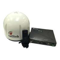
Visual overview of the Fleet One terminal's components and connections.
Lists of standard package items and optional accessories with order codes.
Overview of the three main units of the Fleet One User Equipment.
Details of the ADU, its self-tracking function, and internal modules.
Description of the BDU, its role, and interface ports.
Features of the primary handset and its cradle for communication.
General guidelines for installing the Antenna Unit (ADU).
Key considerations for ADU installation, including line-of-sight.
Safety information on RF radiation from the ADU and required separation.
Guidance on minimizing interference from radar and other radio equipment.
Factors affecting signal quality due to obstructions and object size.
Requirements for mounting the ADU on a mast, including kit details.
Step-by-step procedure for mounting and connecting the antenna unit.
Important notes and procedures for selecting a BDU location and mounting.
Instructions for mounting the primary handset cradle and connecting the handset.
Information on connecting output ports such as GPS and GPIO.
Pinout details for the RS-232 serial GPS output.
Description and pinout for the 10-pin GPIO interface.
Procedure for connecting the grounding stud for safety.
Step-by-step guide to inserting the SIM card into the BDU.
Instructions for powering on the terminal and monitoring LED indicators.
How to operate the ON/OFF switch and expected registration time.
Accessing and configuring the terminal through the web console interface.
Guide to logging into the web console with default credentials.
Steps to enable data connection for internet access via PDP context.
Steps to disable the data connection.
Technical drawings showing the physical dimensions and weight of the ADU.
Diagram illustrating the cut-out hole pattern for ADU mounting.
Technical drawings showing the physical dimensions of the BDU.
Technical drawings showing the physical dimensions of the primary handset.
Information on connecting a data connection switch to the GPIO port.
| Brand | Satlink |
|---|---|
| Model | Fleet One |
| Category | Marine Radar |
| Language | English |