SATLINK FLEET ONE Installation Manual Ref: SL00-01191 Ver: 003
Page 26 of 38
Proprietary Information Not To Be Disclosed Without Written Authorisation From
Satlink S.L., All Rights Reserved
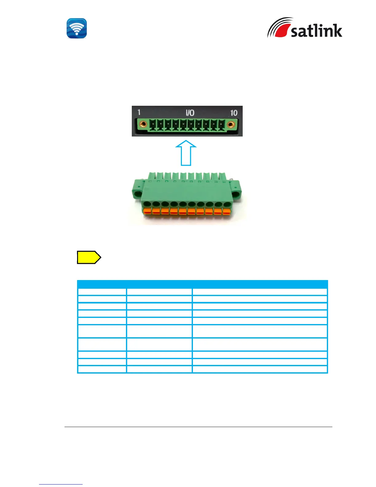
3.1.2 GPIO Port
The BDU has a dedicated 10-pin phoenix connector to provide GPIO (General Purpose
Input/Output) interface to the external devices.
A matching connector is included in the delivery..
GPIO Port Pinout
GPIO - 1 6V To supply 6V DC source.
GPIO - 2 TX_OFF To disable the antenna unit’s transmitter.
GPIO - 3 PDP_ON/OFF To enable/disable the data connection.
GPIO - 4 BUZZER To enable external ringer / buzzer for incoming call.
GPIO - 5 GND To provide grounding for the whole system.
GPIO - 6 REMOTE_ON/OFF_SW For the connection to Remote ON/ OFF switch away
from the BDU.
GPIO - 7 REMOTE_ON/OFF_LED Power Indicator.
GPIO - 8 Reserve Not in use.
GPIO – 9 Reserve Not in use.
GPIO – 10 GND To provide grounding for the whole system.
All wires for the GPIO connector shall use AWG 24 unscreened wire type.
For the data connection switch, refer to Appendix B - GPIO Port