Section 5: Maintenance
SATO CX400 Service Manual PN 9001110A Page: 5-3
MAIN CIRCUIT BOARD REPLACEMENT
The circuit board should never require replacement except in the event of an electrical failure.
Therefore, ensure that the component failure is not sourced elsewhere prior to circuit board
removal.
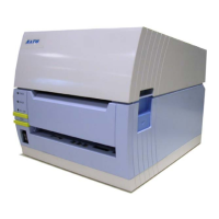
Circuit Board Replacement, Figure 5-2
CAUTION: Printer electronics are susceptable to static discharge.
Ensure appropriate grounding measures are taken before
beginning any activity inside the printer.
1. Turn off power and disconnect power supply cord.
2. Lift cover (Figure 5-2, 1) to expose print assembly (2).
3. Simultaneously, press the two purple buttons (3) located on the top side of print assembly
(2) and pivot upward.
4. Remove applicable front cover/attachment.
NOTE: If the unit has the optional cutter module installed, it may be
removed via a single screw located on the top right side of the
cover. If the peeler cover is installed, two screws located at the
hinge must be removed.
1
2
4
5
6
7
3
Pull Outward and Lift Here

 Loading...