Savant S2/2000 Deployment Guide Copyright © 2019 Savant Systems, LLC
009-1914-00 | 191231 8 of 24
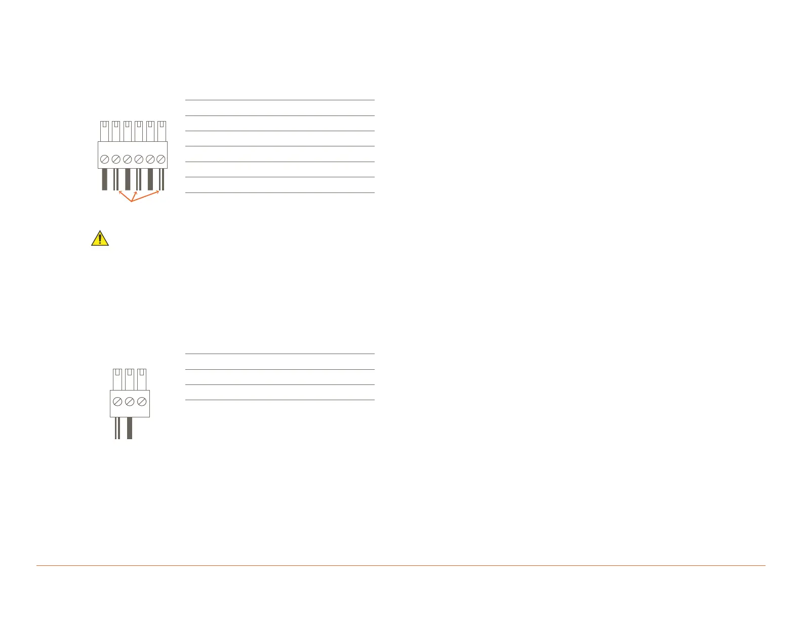
IR Wiring
IR connections are made using 6-pin Screw Down Plug-in Connectors supplied with the Host. The wire slips into the hole and locks with a screw
located at the top of the connector.
Pinout
1
+-
+-
+-
2
3
4 5 6
Use White Stripe
for Positive (+)
Pin 1: IR 1 -
Pin 2: IR 1 +
Pin 3: IR 2 -
Pin 4: IR 2 +
Pin 5: IR 3 -
Pin 6: IR 3 +
IMPORTANT! IR Wiring Precautions
– Ensure that all IR emitters are within 15 feet (4.6 meters) of the controller’s location.
– Use of 3rd party flashing IR emitters with Talk Back is not recommended. These types of emitters can draw voltage away from the IR signal,
resulting in degraded IR performance.
Relay Wiring
Relay ports are used when a device is controlled via a normally open (NO) or normally closed (NC) relay.
Pinout
Pin 1: NC (Normally Closed)
Pin 2: C (Common)
Pin 3: NO (Normally Open)

 Loading...