Savant S2/2000 Deployment Guide Copyright © 2019 Savant Systems, LLC
009-1914-00 | 191231 9 of 24
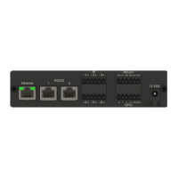
GPIO Wiring
General Purpose Input/Outputs (GPIO) are binary I/O ports used on Savant controllers to trigger an action within the system. Events can control
a device, such as turning on an amplifier (output) or detecting a state change for a device (input) to perform a workflow. Pin 1 is used for input or
output depending on the Component Profile used within the Blueprint configuration.
Pinout
32
1
GPIO 1
Standard
GPIO Using
PD Jumper
Gnd
I/O
PD
Pin 1: GND (Ground)
Pin 2: O/I (GPIO 1)
Pin 3: PD (Pull Down Resistor)
GPIO Pull Down Resistor (PD) Usage
GPIO pins configured as inputs are pulled high to 12V while the Host is booting up. To make the GPIO signal low (< 0.8V) during a Host reboot and/or
a power cycle, attach the GPIO 1 pin to the PD pin. The PD pin is a 1K ohm pull down resistor (to signal ground) which keeps the GPIO output below
0.8V during processor boot times. See item I under Rear Panel for GPIO voltage ratings.

 Loading...