OPM 300 en-GB 86
© Scania CV AB 2020, Sweden
Other
1.
Clean the rocker covers and the area around
them.
2. Remove the rocker covers.
3. Use the turning tool appropriate to the instal-
lation of the engine. Tool 99 309 is used to
rotate the flywheel from the underside of the
engine and tool 2 402 509 is used from the
top side.
4. Start adjusting one cylinder according to the
table. Rotate the flywheel until the correct
engraving can be read on the flywheel. It
may be necessary to rotate it more than 1 rev-
olution.
Rotate the flywheel in the rotational direc-
tion of the engine, which is clockwise
viewed from the front of the engine and anti-
clockwise viewed from the back of the en-
gine.
During a valve transition, the exhaust valve
(the long arm) is closing at the same time as
the intake valve is opening.
The UP TDC engraving on the flywheel is
now visible in the window furthest up on the
flywheel. The DOWN TDC engraving is vis-
ible in the lower window.
5. Read the table on the previous page to see
which valve to adjust.
6. Stick the feeler gauge under the pressure pad
of the rocker arm and check the valve clear-
ance.
7. If necessary, adjust the valve clearance by
a) loosening the lock nut on the end of the
rocker arm
b) adjusting the valve clearance with the ad-
justing screw
c) tightening the lock nut.
8. Mark the rocker arm with the felt-tip pen and
then continue with the next cylinder accord-
ing to the table.
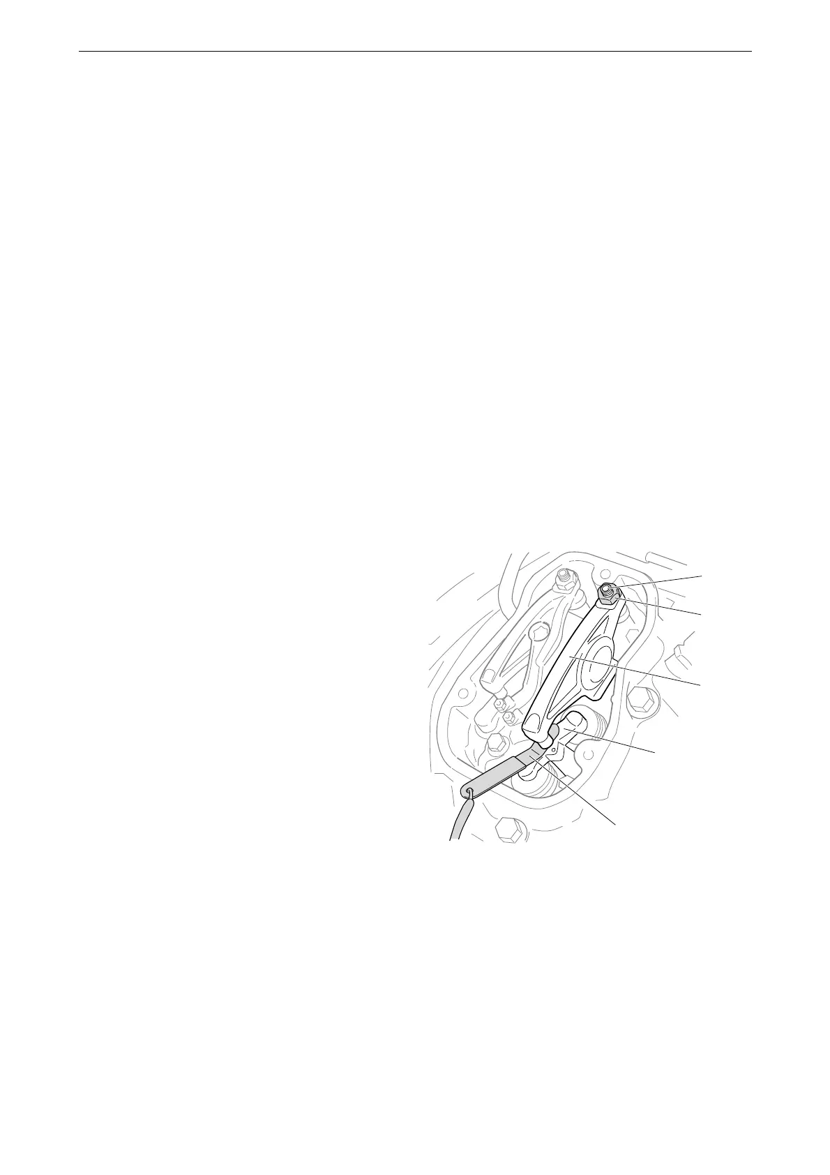
5
4
3
2
1
382 364
1. Adjusting screw
2. Lock nut
3. Rocker arm
4. Valve bridge
5. Feeler gauge