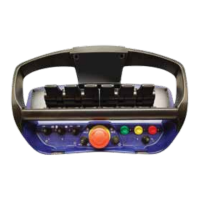
Itemno:1602,1603
Itemno:1604,1605
A
A
A
B
C
B
B
C
Connection
Pin no. Colour / Function
1 Brown / DATA
2 White /GND
3 Blue / RS 232 TX
4 Black / RS 232 RX
5 Grey / Supply output
Connection
Pin no. Colour / Function
1 Brown / DV1
2 White /Power supply
3 Blue / GND
4 Black / CAN_HIGH
5 Grey / CAN_LOW
Cable B (3 meters)
Cable A (3 meters)
Connection
Pin no. Colour / Function
1 Brown / DV2
2 White / LOOP1_OUT
3 Blue / LOOP1_IN
4 Black / LOOP2_OUT
5 Grey / LOOP2_IN
Cable C (3 meters)
5- pole male
M12 connector
5- pole
male
M12 connector
5- pole
female
M12 connector
A
B
5.8 Connection schematics for Central Unit G3B
The Central Unit G3B is equipped with either 2 or 3 circular M12 5-pole connectors (check item no).
The drawing below declares Pin-assignments for both versions of the Central Unit G3B
Document type Document number PageRev
Service Manual S071 C
22 of 46

 Loading...