Cable A
Cable C
Cable B
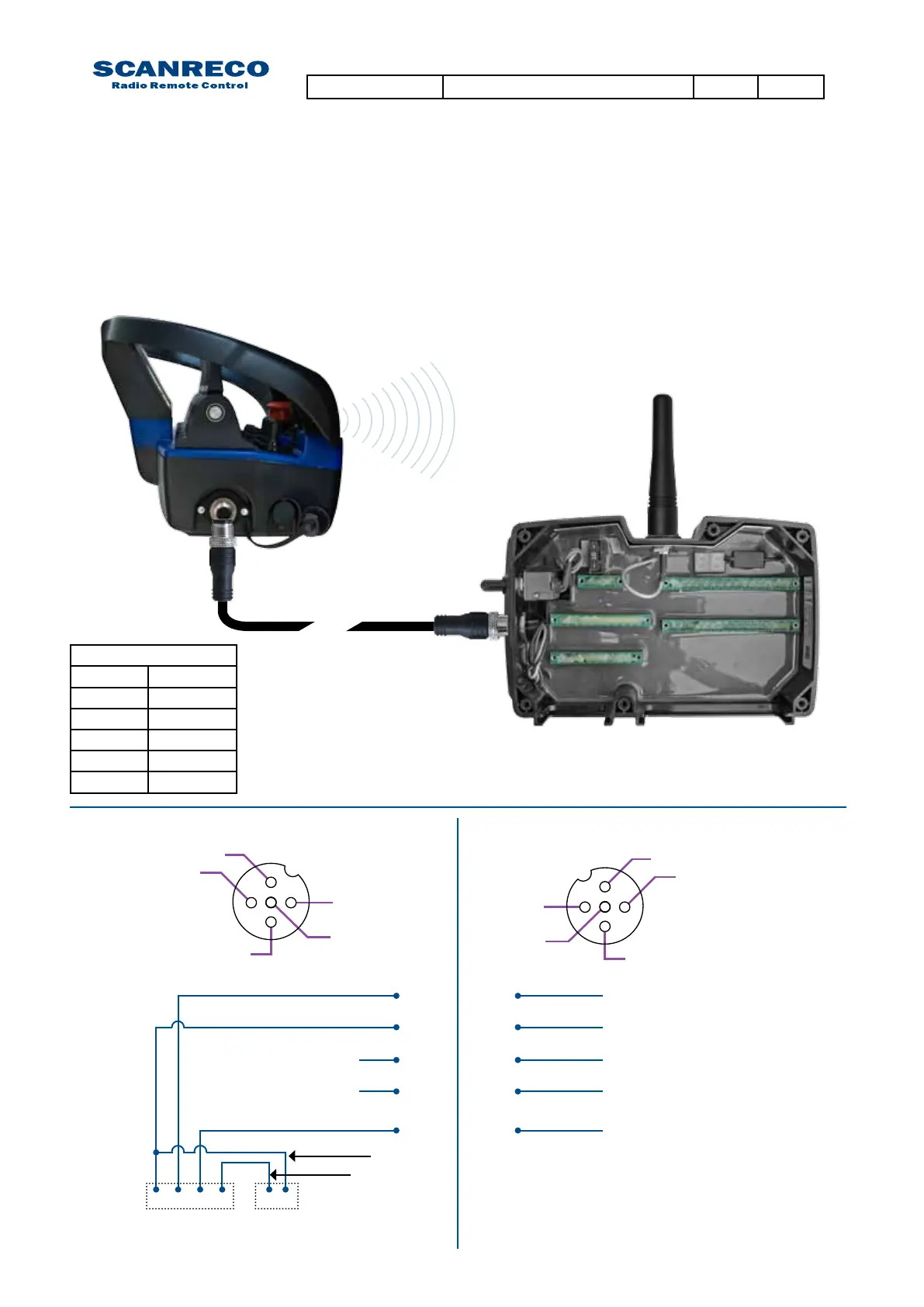
4.4 Cable or radio communication
4.5 Cable connection schematics
Cablecommunicationhashigherprioritythanradiocommunication,ifacablelinkispresent
betweenthePCUandCentralUnitthiswillbedetectedbythesystem,disablingradiocommunica-
tion.
3
3
4
4
5
5
2
2
1
1
Standard 10m cable connector
Portable Control Unit Pin assignments Central Unit G2B/G3B Pin Assignments
11
1 2 3 4
22
33
44
55
Brown / Data
Brown / Data
White / GND
White / GND
n/a
n/a
Blue / RS 232 TX
Black / RS 232 RX
Grey / Supply output
Grey / Supply output
+
_
Battery
Terminal
4-pole main print
card connection
5- pole male
M12 connector
5- pole female
M12 connector
Orange
White
Cable connection
Pin no. Wire color
1 Brown
2 White
3 Blue
4 Black
5 Grey
Document type Document number PageRev
Service Manual S071 C
13 of 46

 Loading...

