8 Radio
8.1 General description
8.2 Determining radio quality
8.3 Radio channel / Frequency
8.4 Range
Radio is used as a bus link for data packages between the transmitter (Portable Control Unit) and
receiver(CentralUnit),theradiocontinuouslytransmitsthepositionsoftheanalogueanddigital
inputs available on the Portable Control Unit to the Central Unit for further processing.
Thedigitalizeddatatransferprotocolusesahighsecuritylevelforvericationofeachdatapack-
age,nolossofindividualfunctionsduetoradiointerferencescanoccur.
The unique ID-code held in the Portable Control Unit ensures that the system can not be operated
unintentionally by other Control Unit.
The transmission allows interferences to some extent as long as multiple data packages are not
interfered successively.
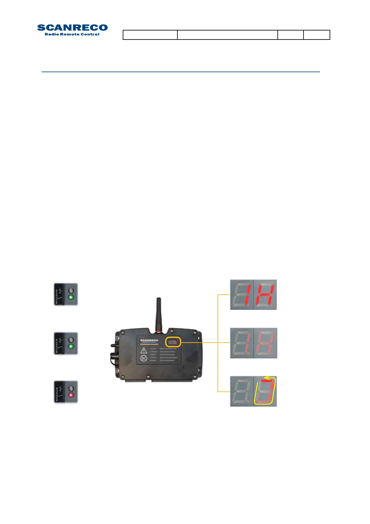
TheradioqualitycanbedeterminedbytheexternalstatusLEDand/ortherst7-segmentonthe
LED-display during radio communication
WhenanoptimalcommunicationisacquiredtheexternalStatusLEDwillbexedgreenandthe
Central Unit LED-display will indicate “1x” (x being dependent on program setting).
Shortinterruptionsandlossesofdatapackageswillbeindicatedbyirregularashesofthese
indicators,anincreasingintensityofashesindicatesadecreasingradio
reception.
Notethatirregularashesisacommonoccurence,unlesstheycauseaninteruptionincommuni-
cation they should not be considered a cause for concern.
Refer to separate document for radio channel used in your region
Refer to separate document for radio channel used in your region
Fixed indications
Fixed green
Flashing green
(Irregular)
Fixed red
Irregularashes
Standby
NOTE:
Insuchcasesthatalockedfrequencyisusedthesecond7-segmentindicationwillbedifferent,
check chapter 6.2 for further information.
Document type Document number PageRev
Service Manual S071 C
30 of 46
 Loading...


