9.1 General description
9.2 Activating diagnostics mode
Adiagnosticsmodehasbeenmadeavailableastodiagnoseandmanagethesystem,theLED-
display is required to be monitored during diagnostics and will allow operator to read out recently
occurrederrorcodes,outputcharacteristicsandprograminformationinordertodiagnosethe
system.
Note that the LED-display is required to be monitored during diagnostics mode.
Do as follows:
1. Remove the battery pack. Connect the cable between the Portable Control Unit and turn off the
Central Unit via the R/M-switch.
2. Activate the Central Unit in REMOTE mode.
3. Press the Portable Control units On-button once.
-The Power-LED should be illuminated
4. Produce impulses in very quick succession with the Micro-toggle to the LEFT (MICRO-ON direc-
tion) 15 times or until the Central Units LED-display indicates D:i – 0:0.
5. Diagnostics mode is now active!
Thediagnosticsmodeconsistof8differentmenus’thatcanbetoggledusingtheon-button,
onceamenuisenteredthecurrentvaluesforthatspecicparameterispresentedintheLED-
display.
To exit diagnostics mode press Stop-button on Portable Control Unit.
9 Diagnostics mode
Ifactivationfails,the4thstepmayhavebeendonetooslow,thetogglehastobedonewitha
maximum0,5secondinterval.
Attention:
Notethatsystemwilloperateoutputsasinnormaloperationalmode,real-timevalues(where
available) are shown in the LED-display.
Notethatbyenteringthediagnosticsmode,theMicrofunctionhasbeenactivatedandanalogue
outputsmayoperatereducedspeeds,iffullspeedsaredesired;pressMicro-toggletotheright
once (MICRO-OFF direction).
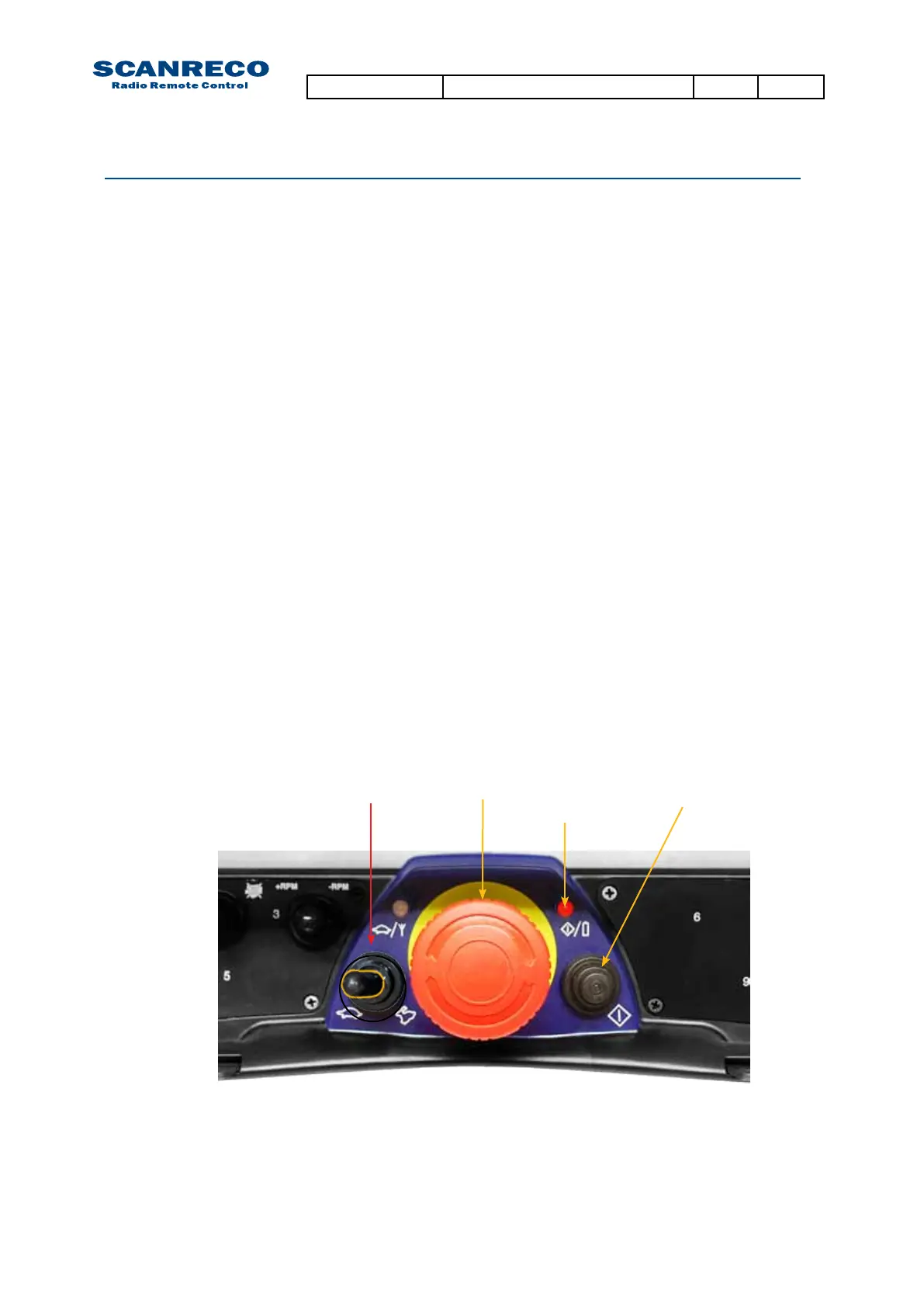
Stop-button On-button
Power-LED
Micro-toggle
Document type Document number PageRev
Service Manual S071 C
31 of 46
 Loading...


