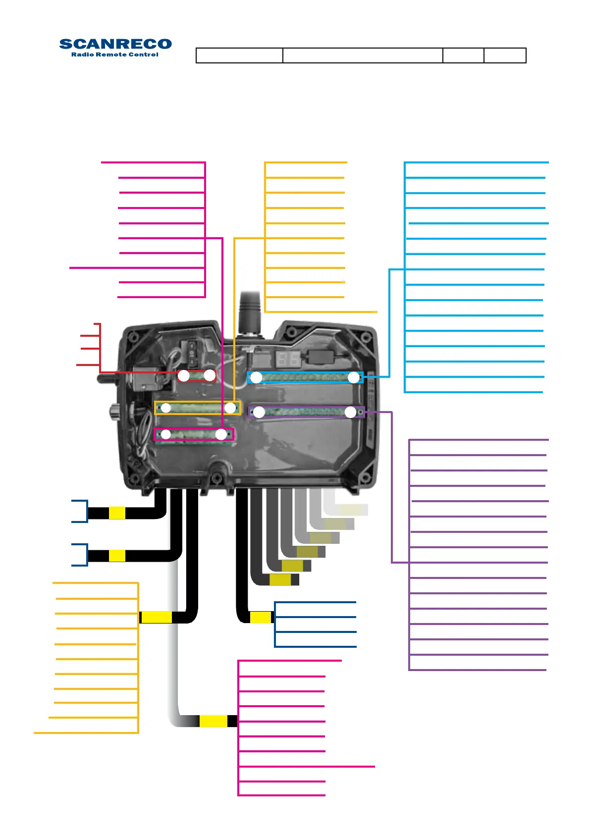
The drawing below declares access points for each available input and output both from the inside
terminal (above) and the standard cable kits (below). Standard cable wire number/marking is also
declared.
5.6 Terminal schematics for voltage controlled Central Unit G2B
EX 1
11 Input supply +VDC
10= Digital input 3
9= Digital input 2
8=Digital input 1
1= Digital output 1
3= Digital output 3
2= Digital output 2
4= Digital output 4
5= Digital output 5
6= Digital output 6
7= GND
11 Input supply +VDC
10= Digital input 310= GND
9= Digital input 2
8= Digital input 1
7= GND
6= Digital output 6
5= Digital output 5
4= Digital output 4
3= Digital output 3
2= Digital output 2
1= Digital output 1
4 = DV-
3 = DV+
2 = GND
1 = + Supply
1= Supply
1= DV+
2= GND
2= DV-
+/-
DV
1
1
16
17 32
1 = 1 Module supply voltage
17 = 5 Module supply voltage
2 = 1 Regulated supply voltage
18 = 5 Regulated supply voltage
3 = 1 GND
19 = 5 GND
4 = 1 Error input (optional)
20 = 5 Error input (optional)
5 = 2 Module supply voltage
21 = 6 Module supply voltage
6 = 2 Regulated supply voltage
22 = 6 Regulated supply voltage
7 = 2 GND
23 = 6 GND
8 = 2 Error input (optional)
24 = 6 Error input (optional)
9 = 3 Module supply voltage
25 = 7 Module supply voltage
10 = 3
Regulated supply voltage
26 = 7 Regulated supply voltage
11 = 3 GND
27 = 7 GND
1 = Module supply voltage
12 = 3 Error input (optional)
28 = 7 Error input (optional)
2 =
Regulated supply voltage
13 = 4
Module supply voltage
29 = 8 Module supply voltage
3 = GND
14 = 4
Regulated supply voltage
30 = 8 Regulated supply voltage
4 = Error input (optional)
15 = 4 GND
31 = 8 GND
16 = 4 Error input (optional)
32 = 8 Error input (optional)
1
4
11
1
2
3
4
5
....
8
9= Digital output 14 / Serial out
8=
Digital output 13 / Digital input 4
7= Digital output 12
6= Digital output 11
5= GND
4= Digital output 10
3= Digital output 9
2= Digital output 8
1=
Digital output 7
1
10
9= Digital output 14 / Serial out
8=
Digital output 13 / Digital input 4
7= Digital output 12
6= Digital output 11
5= GND
4= Digital output 10
3= Digital output 9
2= Digital output 8
1=
Digital output 7
10= GND
EX 2
Document type Document number PageRev
Service Manual S071 C
20 of 46

 Loading...

