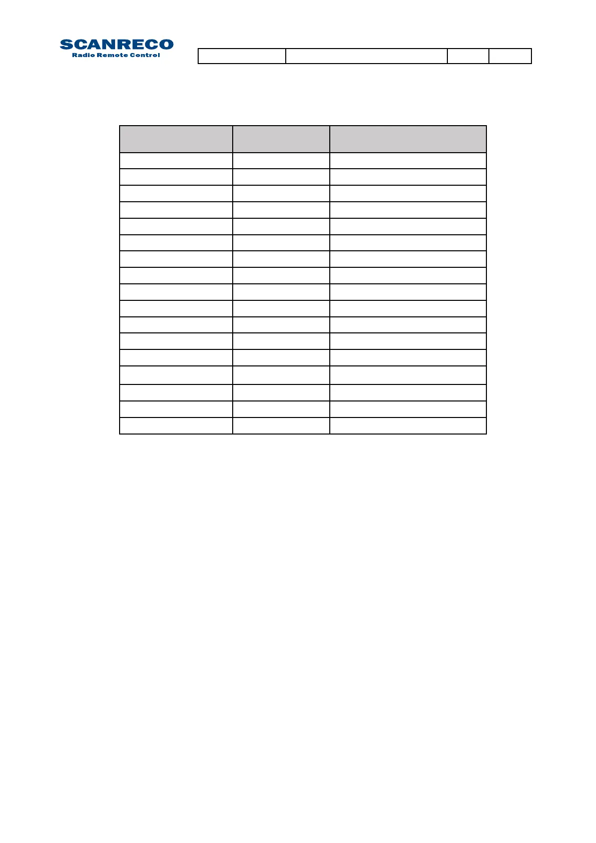
10.3 Table / Programming options
Position via
CU LED Indication
PCU Acoustic signal
(L=Long,S=Short)
Meaning
P:O - 0:0
1L
Start / Default position
P:O - 0:1
1S
Direction
P:O - 0:2
2S Start value SET1
P:O - 0:3
3S Stop value SET1
P:O - 0:4
4S Micro value SET1
P:O - 0:5
1L,1S Ramp delay up SET1
P:O - 0:6
1L,2S Ramp delay down SET1
P:O - 0:7
1L,3S Start value SET2
P:O - 0:8
1L,4S Stop value SET2
P:O - 0:9
2L,1S Micro value SET2
P:O - 1:0
2L,2S Ramp delay up SET2
P:O - 1:1
2L,3S Ramp delay down SET2
P:O - 1:2
2L,4S Start value SET3
P:O - 1:3
3L,1S Stop value SET3
P:O - 1:4
3L,2S Micro value SET3
P:O - 1:5
3L,3S Dump valve delay time
- Return to position 00
10.3.1 Position 01 - Direction
10.3.2 Position 02 - Start speed SET1
For individual adjustment of the direction of lever movement
Available values
0 or 1 (Normal or reversed direction)
When actuating a lever/joystick the LED-display will indicate which output that is active and its cor-
responding direction.
Example:
1:b – 0:1 meaning reversed direction is enabled for output 1
For individual adjustment of start speed
Available values:
Values ranging from 1-100
When activating a lever/joystick the LED-display will indicate which output that is active and its corre-
sponding start speed.
Example:
2:A – 2:0 meaning that the start speed is set to 20% of the maximum velocity on output 2A
10.3.3 Position 03 - Stop speed SET1
For individual adjustment of stop speed
Available values:
Values ranging from 1-100
When activating a lever/joystick the LED-display will indicate which output that is active
and its corresponding start speed.
Example:
3:b – h:I meaning stop speed is set to 100% of maximum velocity on output 3B
Document type Document number PageRev
Service Manual S071 C
37 of 46

 Loading...