www.scheppach.com / service@scheppach.com / +(49)-08223-4002-99 / +(49)-08223-4002-58
|
25
890
1260
1760
2600
The V-belt must lie in the same groove on the
upper and lower drive pulley.
with an interlock switch (27). The interlocking
gearing covers (21) are closed. The device can-
not be switched on if a gearing cover (21) is not
7. Loosen the locking screw (22) and lower the lever
with the motor unit to tighten the V-belt.
8. Tighten the locking screw (22).
9. Close the gearing covers (21). Secure the gearing
covers with the locking screws (20).
Securing the workpiece
Securing with the 4-prong centre tip (1) and tail-
stock (5) (Fig. 1)
1. Draw a diagonal line at both ends of the work-
piece to locate the centre. The centre is where
the lines meet.
4-prong centre tip and tailstock are to meet the
workpiece. This ensures a better hold.
2.
diagonal to enable the 4-prong centre tip (1) to
grip better.
3. -
4-prong centre tip (1) into the workpiece with a
Take
care to protect the thread of the 4-prong centre tip
(1) with a wooden board, for example.
4. -
piece again.
5. Then (re)mount the 4-prong centre tip (1) onto the
device.
4-prong centre tip can be found in the chapter
6. Position the workpiece on the 4-prong centre tip
(1). -
gages with the notch, otherwise secure clamping
is not guaranteed.
7. Loosen the lever (8) of the tailstock.
8. Slide the tailstock towards the 4-prong centre tip
to clamp it.
Mounting the face plate
1. To
do this, place the two open-ended wrenches (16)
on the drive shaft (19) and on the 4-prong centre
tip (1) and unscrew the 4-prong centre tip (1).
2.
open-ended spanner (16).
3. Screw the face plate (13) onto the drive shaft (19).
10. Operation
Select speed (Fig. 4)
m ATTENTION!
The mains plug shall not be plugged in when ad-
justing the speed.
Select the correct speed:
• -
crease the speed as the weight of the workpiece
increases.
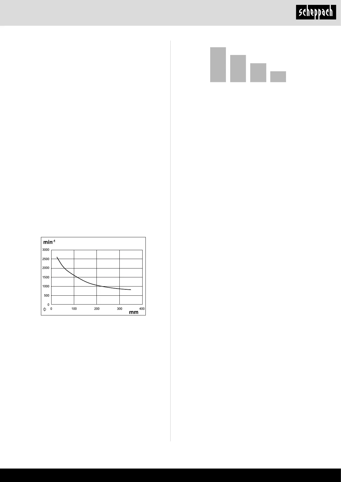
• The selection of the correct speed depends on
several factors, e.g. material, diameter, length and
unbalance of the workpiece.
a low speed for hard timber, non-round, long or
large-diameter workpieces.
•
The workpiece diameter is indicated on the x-axis.
the curve.
1. Loosen the two locking screws (20) on the two
gearing covers (21).
2. Open the gearing covers (21).
3. Loosen the locking screw (22) of the motor unit
4.
to relieve the load on the V-belt (26).
5.
screw (22).
6. Place the V-belt (26) in the desired groove of the
 Loading...