Chapter
2
Funcrionai
Overview
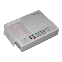
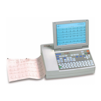
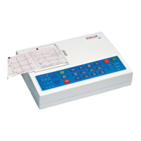
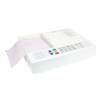
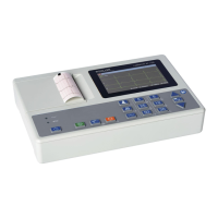
SCHILLER
AT-1
3-Channel
ECG
Unit
SERVICE
AGWDBOOK
Issue
3
September
1999
Control
and
Power
Supply
board
LMK
I1
-
L
Power
Supply
The
mains
suuply
is
full
wave rectified
to
produce
an
unregulated
dc
supply
of
approximately
35V(+U).
This voltage
is
used
by
a
switched voltage generator
to
produce
+UD
(13.jV).
+UD
charges the battery wnen
mains
is
connected. When
mains
is
not connected,
+UD
is
the battery
voltage.
An
ON/OFF
control logic switches
+UD
to
three voltage regulators. The unit
is
switched
on
directly from the keyboard
and
then held
on
from the CPU (signal
!J,PO~.
Detection
of
overvoltage
on
either
the
5.2V
or
24V
supplies directly switches
the
unit
off.
Similarly when
an
undervoltage
is
detected
on
+us
(indicating over current) the unit
is
directly switched
off.
The
mains
LED
is
lit directly when
mains
is
connected. The same circuit
also
monitors
the
switched
dc supply
(+US)
and
activates signal +BAIT when the
unit
is
switched
on
and
mains
is
not
connected (i.e.
the
unit
is
running
on
battery power).
A
Battery low signal
(BLOW)
is
generated when battery voltage
(+US)
falls
to 11.3V. A circuit
compensates
for
voltage drop when the printer stepper motor is active
and
the
Blow signal
is
active
only
at
10.3V.
Note:
The
bartery voltage
is
also
monitored directly
by
the CPU which switches
the
unit
off
(p0FF)
when
the
voltage
falls
below approximateiy
9.4V.
CPU
and
Processing
Circuits
Overall control and coordination
of
the
AT-1
is
by 68332 CPU which performs
all
timing
and
control functions.
Memory
Program
Memory
An EPROM contains the unit software. The EPROM
has
128
kByte
of
memory.
Static
RAM
Memory
The
RAM
memory stores
the
ECG
data
and comprises
two
128
kbyte
RAM
chips.
All
data are lost
when the unit
is
switched
off.
Serial
EEPROM
The serial
EEPROM
(U12)
stores the
unit
base settings.
-.
..
.
Page
2.4