Chapter
4
Module
Removal
and
Revlacement
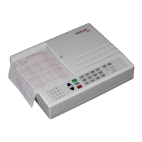
SCHILLER
AT-1
3-ChaMel
ECG
Unit
SERVICE
WDBOOK
lssue
3
Seprember
1999
ECG
Interface
Board
iMK
11-
2
The ECG Interface
is
mounted above the Control
and
Power Supply boardMK
11-1
andis secured
to
six
spacers.
Prerequisite
The
Warnings
and Cauuons at
the
beginning
of
the Gapter
must
be
observed.
The
Top
Assembly
must
be
removed
and
all
external cable assemblies disconnected.
Took
and
Test
Equipment
Cross-bladed posi-dnve screwdnver
Parts
ECG
Amplifier board.
Part
number
as
detailed in Chapter
6.
Board
Removai
CAUTION
THE
ECG
AMPLIFIER
CONTAINS STATIC
SENSnIVE CMOS
COMPONENTS. OBSERVE
ANTISTATIC PRECAUTIONS.
To
remove
the
ECG Amplifier proceed
as
follows:
1.
Unscrew
the
six
screws
securing
the board to
the
spacers.
2.
Gently
raise the board
to
gain access
to
the cable assembly
to
the
Control board and remove
the
connector. Remove
the
board.
Board
Replacement
1.
Place the ECG Amplifier board component side down over
the
six
spacers and connect
the
cable assembly to the Conrrol board
MK
1-1
1.
Place
the
board
so
that
the
patient cable
connector
is
positioned
in
the cutout
on
the
side panel.
2.
Secure the board to the
six
spacer supports
with
the
retaining screws.
Checks
and
Tests
after Repiacement
To
prove
the
integnty
of
the repaced board carry out the following functional
check
procedure:
Switchon
the
unit
andconnectaSCHELER pauentcable to theECGconnector. Connectasuitable
patient
simulator
io
the
ECG connector
and
press
'MAN
START.
Ensure that
all
the
leads
are
printed.
Page
4.
I0