Chapter
4
Module
Removal
and
Replacement
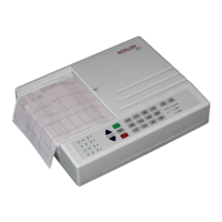
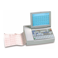
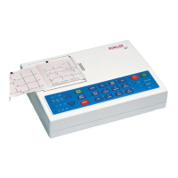
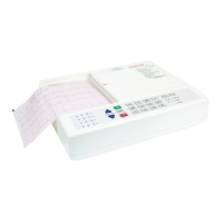
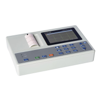
SCHILLER
AT-I
3-Channel
ECG
Unit
SERWCE
HWDBOOK
issue
3
September
I999
Opening
the
case
Top
Assembly
Replacement
To
1.
2.
3.
4.
5.
6.
7.
8.
replace
the
Top Assembly proceed
as
follows:
Check
that
alI
boards
and components
are
fly secured. Check for loose screws. Ensure
that no screws or foreign bodies are loose
in
the
bottom
of
the
case.
Inspect
all
the
internal cable assemblies and ensure that they
are
in
good condition and that
no visible damage can be seen.
Ensure
that
no
cable assemblies are
strained.
crushed or
caught.
Ensure
that
all
connectors are firmly
home.
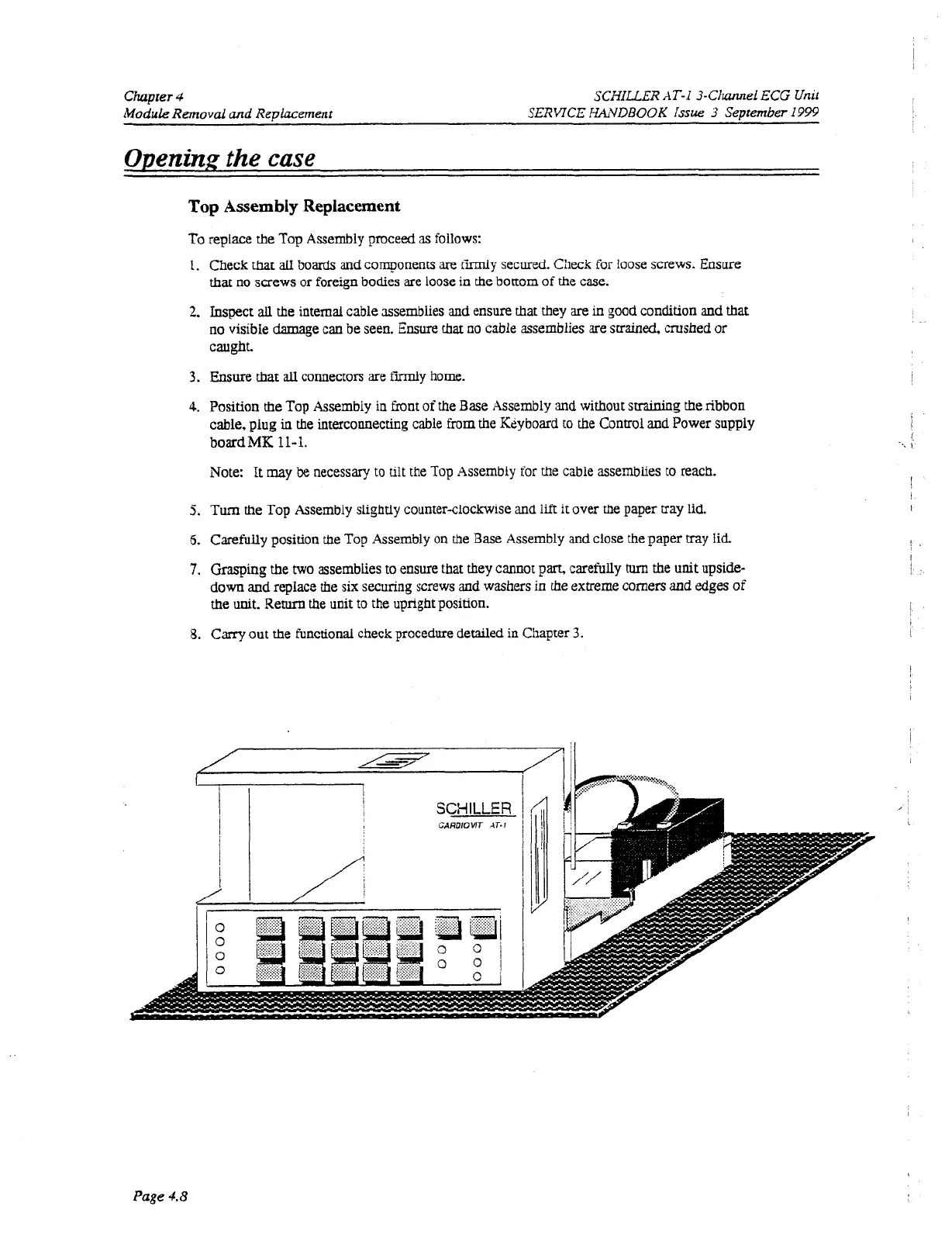
Position
the
Top Assembly in
front
of
the
Base Assembly and without
straining
the
ribbon
cable, plug
in
the interconnecting cable
from
the
Ktiyboard to the Control
and
Power supply
bOXdMK
11-1.
Note: It may
be
necessary
to
tilt
the
Top
Assembly for the cable assemblies
to
reach.
Turn
the
Top Assembly slightly counter-clockwise and lift
it
over the paper tray
lid.
Carefully position the Top Assembly on the Base Assembly and close the paper tray
lid.
Grasping
the
two
assemblies
to
ensure that they cannot
part,
carefully
tum
the
unit
upside-
down and replace
the
six securing screws and washers
in
the
extreme corners and edges
of
the
unit.
Return
the
unit to
the
upright position.
Cany out
the
functional check procedure
detailed
in Chapter
3.
!
I
i
Page
4.8
 Loading...