SCHLLLER
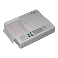
AT-1
3-Channei
ECG
Unir
SERVICE
HANDBOOK
Issue
2
Julv
1998
Chapter
8
Glossary
Acro
n
vms
LCDKONT
LCDW
LD
1.2.3.4
LDS
LED
(0.3
LEDB
LEDMAINS
LOE
LP
LSRAM
LWE
M
MCLK
IMOD
MOFF
MON
m
NMI
OFF
PDS
PM
PMARK
PMPON
PMNEG
PMPOS
PWM
QmG
Eu
RAS
RES
LCD contrast
-
sets
the
-18
V
voltage level (from which
the
LCD
backlight
power
is
generated) and thus the contrast
of
the screen.
LCD Write.
Lower
LO
dam
Lower
data
suobe.
Operate signals to
the
LED
indicators on the keyboard.
Battery
LED.
Signal
indicating
mains
connected
-
to operate
LED
indicator on the
key board.
Lower output enable
-
con,uol
si,.nal
for static
Ram.
Line synchronisation.
Lower
output
enable
-
control
signal
for static
RAM.
Lower Write Enable
-
control
signal
for
Static
Ram.
LCD control signal derived
from
EM.
Motor Clock
-
speed control for the printer motor.
Conuol signal from the battery charging circuir
-Motor
off.
.Motor
On
-
Pnnter motor enable signal.
Mains
supply.
Non-maskable intermpt
-
interrupt for U47 (Schiller gate
array)
activated by the reset button.
Off
signal from the
OFF
key to switch
off
the power supply.
Conuoi signal derived from
&'vl
(unity waveform
1/2
&&I
frequency).
Paper mark signal.
Paper mark detection signal.
Pacemaker detection pulse.
Pacemaker negxive
-
indicates the trailing edge
of
a
pacemaker pulse.
Pacemaker positive
-
indicates the leading edge
of
a
pacemaker pulse.
Pulse Width AModulation
QRS trigger
-
output signal.
Right
.Ann.
Row address strobe.
Reset.
Page
8.5