10
Montage- und Betriebsanleitung für 2-Backen-Parallelgreifer
PGN-plus mit Werkzeugschnittstelle HSK/KM/Capto
Operating manual for 2-Finger Parallel Gripper
PGN-plus with tool interface HSK/KM/Capto
1. Entfernen Sie die Druckluftleitungen.
2. Drehen Sie die Schrauben (Pos. 47) heraus und entfernen Sie
dann das Abdeckblech (Pos. 5).
3. Markieren Sie die Einbaulage des Kolbens (Pos. 3/ 8) und der
Grundbacken im Gehäuse (Pos. 2/7).
Achtung !
4. Spannen Sie den Greifer zwischen den Grundbacken
(Pos. 2/7) und dem Deckel (Pos. 9) so in den Schraubstock
ein, dass Sie die 4 Schrauben (Pos. 46) noch entfernen
können. Drehen Sie die Schrauben (Pos. 46) heraus. Danach
entspannen Sie den Schraubstock vorsichtig bis die Druckfeder
entspannt ist. Nehmen Sie den Deckel und die Druckfeder ab.
Fahren Sie fort wie beim Greifer ohne Greifkraftsicherung (von
Punkt 5 bis 9).
Der Zusammenbau erfolgt in umgekehrter Reihenfolge. Beachten
Sie dabei die Kapitel 7.1 und die Schraubenanzugsmomente
Kapitel 7.3.
7.2.1 Version with ”Internal gripping force safety system“
1. Remove the compressed air lines.
2. Undo the screws (Item 47) and then remove the cover plate
(Item 5).
3. Mark the position of the piston (Item 3/8) and the base jaws
(Item 2/7) in the housing.
cAutIOn !
In the case of the version with the ”internal safety
system“, the cover (Item 9) is spring-loaded.
4. Clamp the gripper into the vice between the base jaws
(Item 2/7) and the cover (Item 9) in such a way as to be able
to remove the 4 screws (Item 46). Fully undo the screws (Item
46). Then open the vice carefully until the tension on the
compression spring (Item 25) is released. Remove the cover
and the compression spring.
Continue as in the case of the gripper without gripping force safety
system (from paragraphs 5 to 9).
Carry out assembly in the reverse order from the above. When
reassembling, observe the instructions in chapter 7.1 and the
screw breakaway torque in chapter 7.3.
7.3 Screw breakaway torques
Type Pos. / item 40 Pos. / item 41 Pos. / item 45 Pos. / item 46
PGN-plus 50 0.8 Nm 1.3 Nm 2.2 Nm 1.3 Nm
PGN-plus 64 6 Nm 1.3 Nm 10 Nm 1.3 Nm
PGN-plus 80 10 Nm 3 Nm 17 Nm 3 Nm
PGN-plus 100 17 Nm 3 Nm 17 Nm 3 Nm
PGN-plus 125 24 Nm 6 Nm 41 Nm 6 Nm
PGN-plus 160 48 Nm 6 Nm 83 Nm 6 Nm
PGN-plus 200 75 Nm 6 Nm 116 Nm 25 Nm
PGN-plus 300 120 Nm 6 Nm 150 Nm 25 Nm
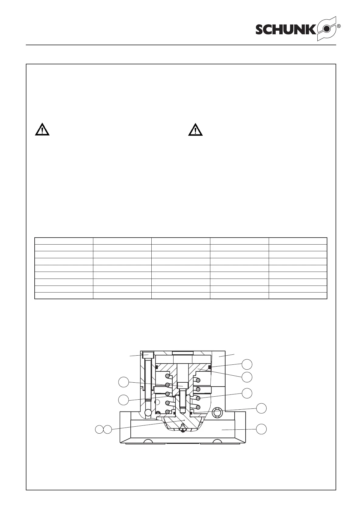
8. Zusammenbauzeichnungen 8. Assembly drawings
8
50
33
30
Schraube / Screw
25
Vorrichtung / Device
3
45
31
10

 Loading...