SPECIFICATIONS
MECHANICAL PARTS REMOVAL/REPLACEMENT
19
SCIFIT Scientic Solutions For Fitness SCIFIT Scientic Solutions For Fitness SCIFIT
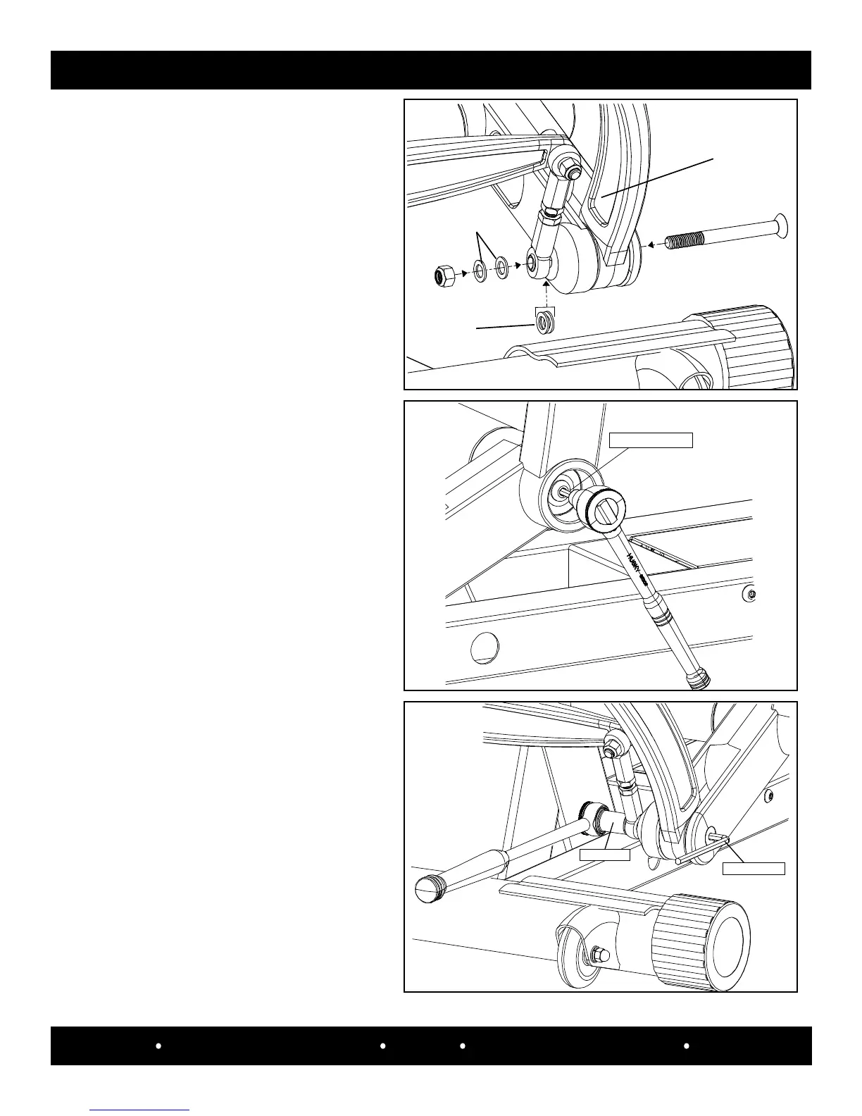
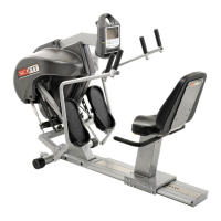
Between the
pivot link and
lower outer
handle assembly
Outside the
pivot link
Assembly
link
Secure the pivot link and the assembly link
to the lower outer handle with a 1/4” allen
hex and a torque wrench set at 720 in/lbs.
Step 3:
5/8” Socket
1/4” Allen Hex
Torque Wrench
Align the assembly link and the pivot
link with the bottom holes of the outer
handle and loosely secure them with
the h ardware previously removed.
Note: Verify the washers are placed in
the correct location.
Step 4:
Return to the button head screw, then use a
7/32” allen hex and tighen it.
Step 5:
7/32” Allen Hex