SPECIFICATIONS
MECHANICAL PARTS REMOVAL/REPLACEMENT
31
SCIFIT Scientic Solutions For Fitness SCIFIT Scientic Solutions For Fitness SCIFIT
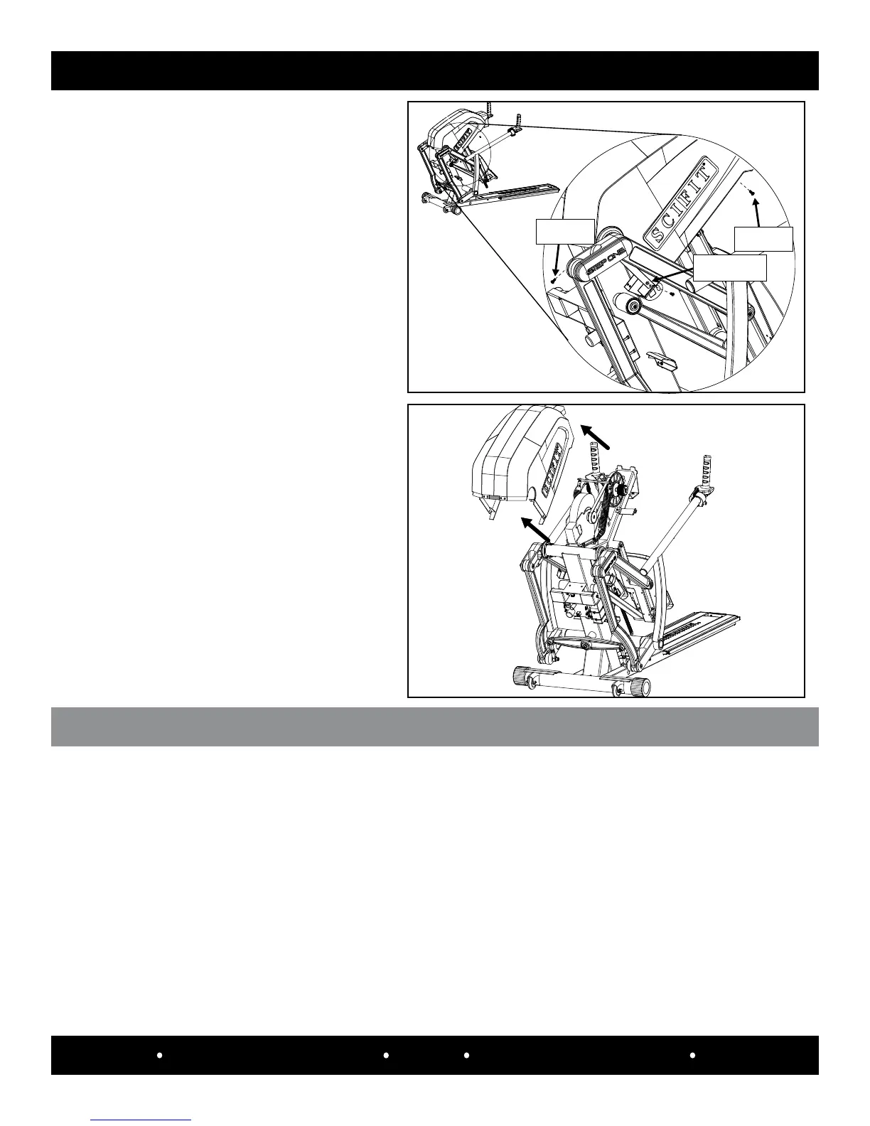
Step 8:
Carefully remove the upper left (#A5625)
and right (#A5626) covers.
SPECIFICATIONS
LoWEr/UppEr covEr rEpLAcEmEnT
Step 1:
Place the upper covers back onto the machine and secure them to the frame with the two upper pan head
screws (#1128957) and two lower at head screws (#1129467).
Step 2:
Place the lower cover back onto the machine and secure it to the frame with the four pan head screws
(#1128957).
Lower Flat Head
Screw Location
Upper Screw
Location
Screw Inside
Cover
Step 6:
Starting on the left side use a phillips
screwdriver to remove the upper pan head
screw (#1128957), the pan head screw
inside the rear of the cover (#1128957)
and lower at head screw (#1129467) that
secure the upper covers to the frame.
Step 7:
Repeat step 6 for the right side.
Step 3:
Reconnect the “Communication” cable and “Step counter” cables to the console, then secure it to the frame
with the two ange bolts (#19651).