Installation ST144-21 C/Ku-Band TVRO
3-26
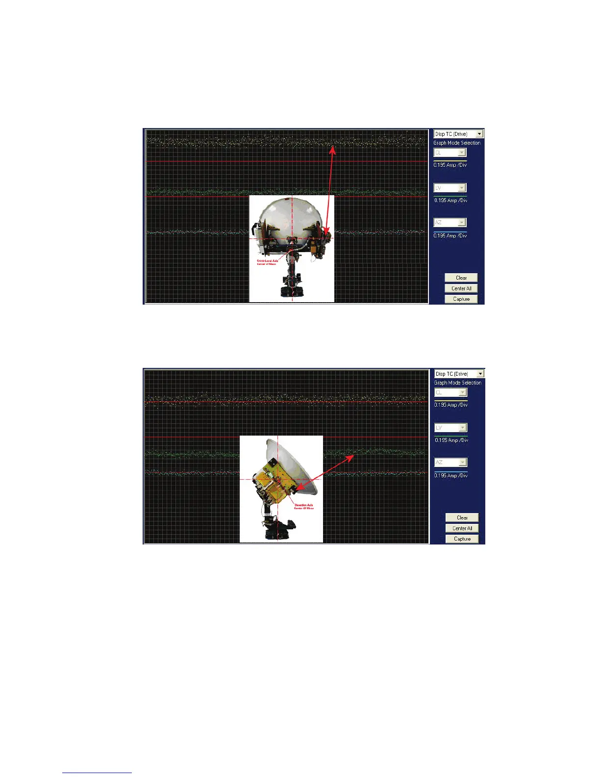
• The Cross Level displayed above the reference line indicates that the CL axis is being driven CCW
(Left in CL).
Example: The antenna pictured in the screen capture below is imbalanced so that it is “Right Heavy”.
The CL trace is plotting above the red reference line, indicating that CCW drive is required to keep
the Cross-Level beam level to the horizon.
• The Level display will plot below the reference line when the antenna requires CW drive (Up in
elevation).
Example: The antenna pictured in the screen capture below is imbalanced so that it is “Front, or
Bottom, Heavy”. The LV trace is plotting above the red line, indicating that the LV axis is being
driven CW to maintain the current elevation position.
• The Azimuth display plots below the red line as the antenna is driven CW and plots above the red
line as the antenna is driving CCW.
3.12. Setup
Refer to the Setup information in the next section of this manual and in the Setup section of your ACU Manual.
 Loading...