ST144-21 C/Ku-Band TVRO Maintenance and Troubleshooting
13-9
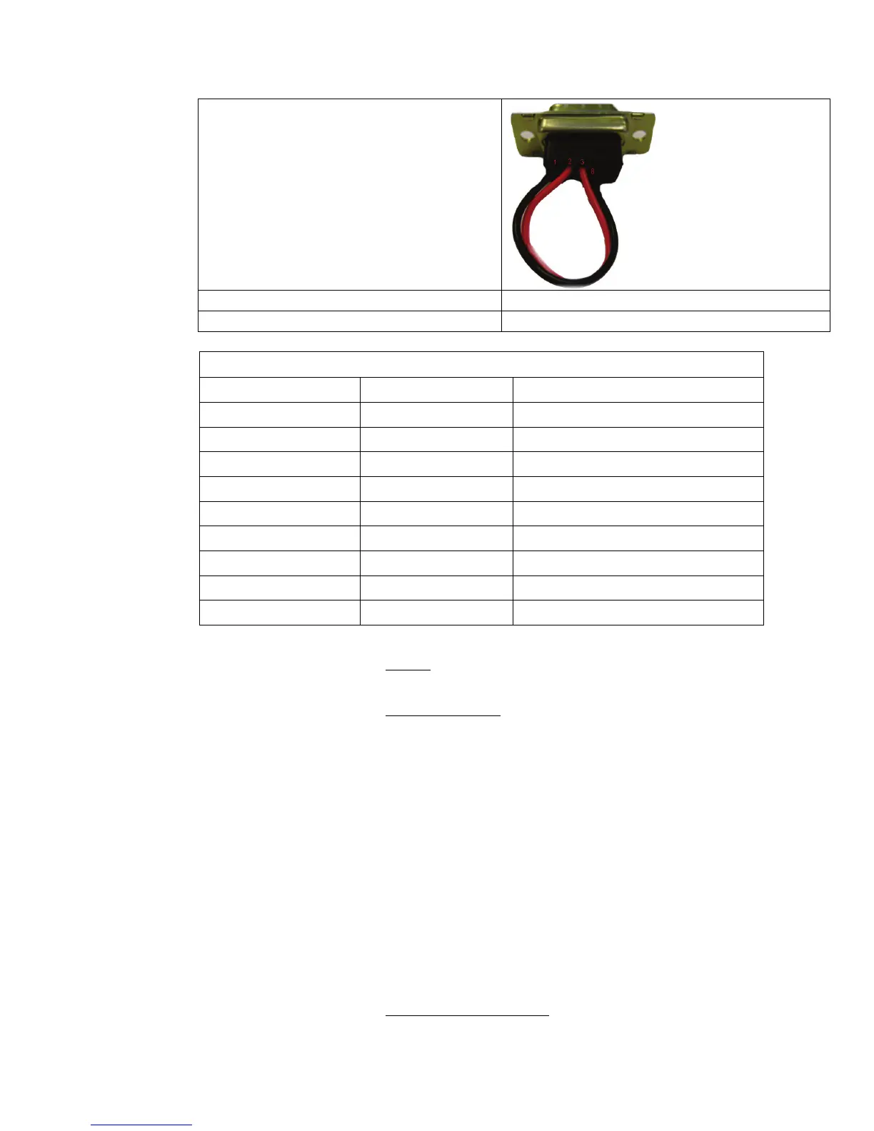
Serial Loopback Connector
Build a Loop Back Test Adapter by Shorting Pin 1
to Pin 8 and Shorting Pin 2 to Pin 3 on a female
DB9(S) connector.
Spectrum Analyzer Capable of handling 100kHz up to 3Ghz & up to 48VDC
SMA “T” splitter or N type “T” splitter Or equivalent cabling
400MHz FSK Modem Fault Reference Table
ADE Modem RSSI BDE Modem RSSI Failure
P= <65, R= <65 P= <65, R= <65 None
P= >65, R= >65 P= >65, R= >65 Receive IF Path
No Response No Response BDE/ADE No Response
No Response P= <65, R= <65 ADE No Response 1
No Response P= >65, R= >65 ADE No Response 2
P= <65, R= <65 P= >65, R= <65 BDE Receive Or ADE Transmit (PED M&C)
P= <65, R= >65 P= <65, R= <65 BDE Transmit Or ADE Receive (PED M&C)
P= <65, R= <65 P= <65, R= >65 BDE Receive Or ADE Transmit (RF M&C)
P= <65, R= >65 P= <65, R= <65 BDE Transmit Or ADE Receive (RF M&C)
13.6.3.1.1.
No failure communication failures between ADE and BDE modems.
NONE:
13.6.3.1.2.
The Following possibly points of failures assumes LED illumination on both modems.
Receive IF Path:
• Modem Configuration
Verify BDE modem and ADE modem are properly configured (jumper block settings).
• Coax Cable failure
Verify continuity on the below coaxes, repair or replace as required.
o BDE Modem to connector bracket (Base Rack Panel Assembly)
o (CFE) BDE to ADE Rx IF (Base Rack Panel to radome Connector bracket)
o Rx N to SMA Adapter (Located on connector bracket at radome base)
o SMA to SMA (From connector bracket to bottom the bottom side of the
rotary joint)
o SMA to SMA (From top side rotary joint to PCU/ADE Modem
• Rotary Joint (Receive channel)
Verify continuity on the receive channel for its entire 360 degree range of motion.
Replace rotary joint if any sector of it has failed.
13.6.3.1.3.
The Following possibly points of failures assumes LED illumination on both modems.
BDE/ADE No Response:
 Loading...