LIMIT SWITCH AND SENSOR BARRIERS
Sensor barriers
This control unit comes with a detection device of motor current absorbtion which allows to
reveal possible obstacles during the opening and the closing of the gate. When this device
intervenes in opening it causes the inversion of the movement for around a second, if it
intervenes in closing it causes the total reopening.
Note1: The ammeter sensitivity is adjustable both in opening and in closing through the
on-board display or through the JOLLY terminal. With high torque the gate reverses after
5 seconds.
Attention: In case of obstacle, if the automatic reclosing is on, the gate will attempt to
close for 3 times, whereupon a start signal will be necessary to re-establish the
movment.
Limit
Switch
CN2
USER 1 - 24V DG
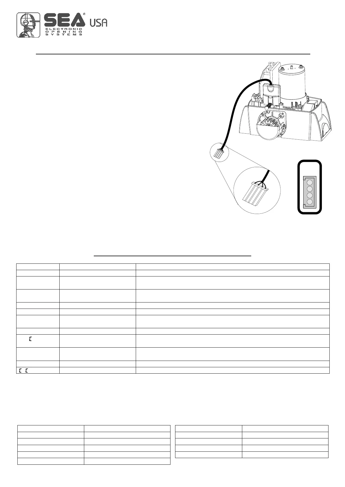
Limit switch
The limit switch can be connected through the special LIMIT SWITCH connector on
the control unit. The control unit can administrate mechanical, inductive and magnetic
limit switches. Only on some special applications il will not be necessary to connect
the limit switches. The control unit will automatically realize if limit switches are
present or not.
1) Through the on-board display or through the JOLLY programmer it is possible to
activate the ani-intrusion function. This function is lied to the presence of at least one
limit switch which, when free, forces the motor to re-close.
Note: if during programming phase the motor and limit switch times should not
be in phase between them, the gate will start in closing, it stops and will not
complete the selflearning of the times, at this point it will be necessary to
switch off the tension and to invert the cables of the motor. The first movement
in selflearning must always be executed in closing.
ATTENTION: When using SEA magnetic limit switches, make sure that the
motor is set on s AG.
U
20
ALARMS INDICATIONS
Flashings Number
9
2
3
6
4
Flashings Number
5
7
6
4 fast
Kind of alarm
Motors fault
Photocell in closing
Photocell in opening
Opening impact
Safety edge
Kind of alarm
Stop
Max. Reached cycles
Closing impact
Limit switch error
Battery voltage fault
F.
BAT
If network is not present
Motors current fault
24V Power supply fault
24Vaux output voltage
Power supply fault
FAUL
FT.24
FT.AU
FT.LI
Sure there are no short circuits on the motor or on the control unit.
Make sure there are no short circuits on the wiring or on the control unit and
no overloads.
Make sure there are no short circuits on wiring or control unit and
no overload.
Check the network or the F1 fuse.
Balanced edge input fault
Self-test photocells fault
Limit switch activation fault
Flashing lamp fault
Max. cycles
F.EDG
F.PHO
FT.f
FT.FL
Y L
Check for a 8.2 Ohms resistive value on the edge input, if not available
enter it, or disable the reading of the 8k2 in the special menu.
Check the photocells operation and / or connections on the control unit.
Check the operation of both limit switches and / or correspondence
between movement direction of the motor and engaged limit switches.
Check connections and / or conditions of the lamp.
Maintain and / or reset the number of performed cycles.
Signals Kind of alarm
Solutions
Note: To exit from the error messages, press OK. If the error persists, make all required checks for the specific error and / or disconnect the
device that generates the error to see if the error disappears.
At each opening and closing of the automation the flashing light will blink. It blinks once per second during opening and twice per second
during closing, while it remains lit during pause.
It is possible to view the alarms also on the flashing light or on the control lamp, simply by observing the number of flashes emitted and
verifying the reference in the table below:
FT.SL
Slave fault Check the connection between MASTER and SLAVE or if the SLAVE board is
actually set as such.
International registered trademark n. 2.777.971
67411535 REV 03 - 05/2013