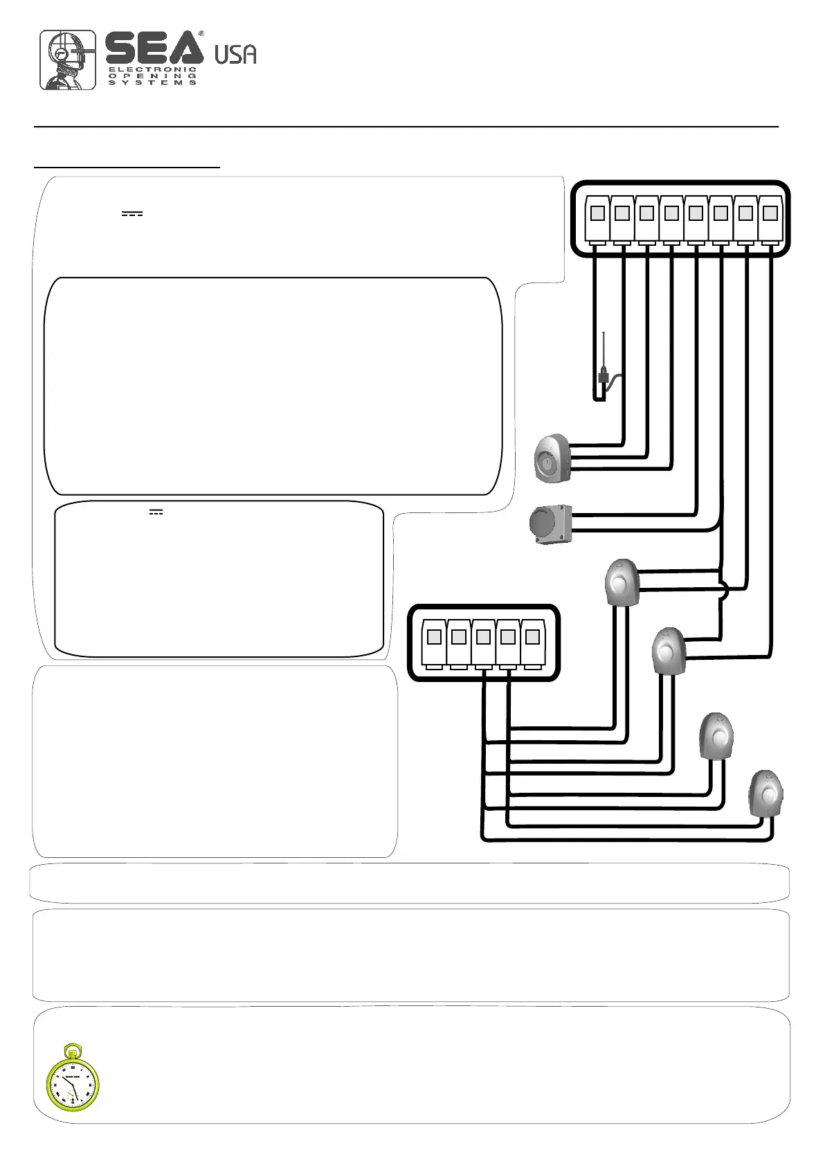
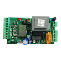
START - STOP - PEDESTRIAN START - ANTENNA -
PHOTOCELL
USER 1 - 24V DG
19
International registered trademark n. 2.777.971
67411535
START (N.O.) The
An impulse given to this contact opens and closes the automation depending onthe selected logic it can be given by a key switch, a keypad,
etc. To connect the other devices refer to the related instructions leaflets. (ie. loop detectors and proximity switches).
Note1: In DEAD MAN logic it is necessary to keep pressed the Start for the opening of the automation.
Note2:
START is connected between the clamps 2 and 3 of the CN 1 terminal.
In 2 BUTTONS logic this button performs the opening.
STOP (N.C.) The STOP is connected between the clamps 2 and 5 of the CN1 terminal .
The pressure on this button immediately stops the motor in any condition/position. A start command is needed to re-start the movement.
After a stop the motor always re-starts in closing.
Photocell 1 and Photocell 2 Connections
Note: If the photocells are not connected, put a jumper between the clamps (6,7,8).
+ = 24V(FL) COM = 0V PH1 = Photocell contact 1 PH2 = Photocell contact 2
Note: For the autotest connect the TX to the 24Vaux clamp and activate the Autotest function.
The standard setting of the photocell 1 is FOTO CLOSE and the one of the photocell 2 is FOTO
OPEN. The photocell 2 can be set also as TIMER (see TIMER function).
Note3: On the Ph.Te menu you can also activate the self-test even on the single photocell.
Can be activated through on-board display or through the Jolly programmer. In both cases it’s a N.O. contact which provoques
the opening of the automation keeping it open until it is activated. When it’s released, the gate attends the set pausing time
and executes the reclosing. The TIMER command can be activated on the inputs FOTO2, START PEDESTRIAN.
Note1: When activated on the pedestrian entry, the pedestrian will be disabled also on the radio transmitter.
Note2: In case of intervention of a security device during the timer (Stop, Ammeter, Edge), to restore the movement it will be
necessary to give a start impulse.
Note3: In case of no power supply with open gate and active Timer the control unit will restore its use, otherwise if during
restore of the power supply the TIMER is not activated it will be necessary to give a start impulse for the reclosing.
TIMER
Antenna
Common
Start
Start ped.
Stop
Common
Photocell 1
CN1
1 2 3 4 5 6 7 8
Photocell 2
RX1
RX2
TX1
TX2
CN1
9 10 11 12 13
Common
24V (FL)
OPTIONS ON FOTO1 and FOTO2 adjustable on on- board display or with
JOLLY terminal.
FOTO CLOSE activation ((los): if occupied, reverses the movement in closing, during
pause it prevent the closing.
Activation repeat pause (rP.PA): If occupied, during pause it recharges the timer of pause.
In closing it reverses the movement.
FOTO OPEN activation (oPEn): If activated the photocell blocks the movement as long as
it’s busy, when released the opening continues.
FOTO PARK activation (par() : in opening it is not active; in pause are activated it
commands the closing when released, otherwise it’s not active; in closing it stops the
movement as long as it is busy, when released the closing continues.
FOTO STOP activation (STOP): When activated before the opening the photocell blocks the
automation as long as it is busy, during the opening it will be ignored. In closing the
intervention of the photocell causes the reopening.
Activation PHOTO CLOSE IMMEDIATELY: The photocell stops the gate as long as it is
occupied in both opening and closing, when released it gives a closing command (Closing
one second after release of the photocell ).
PEDESTRIAN START (N.O.) The pedestrian start can be
connected between the clamps 2 and 4 of the CN1 terminal .
This input allows a partial opening the opening space can be set
through the on-board display or through the JOLLY device.
Note1: The contact for partial opening is a N.O. Contact (Normally
open).
Note2:In 2 BUTTONS logic it is necessary to keep pressed the Start
Ped. to re-close the automation.
Note3: In dead man logic this button executes the re-closing if you
keep it pressed.
Note4: When closed during pause, the gate will reclose only after
this input has been reopened.
TIMER activation: This input can be transformed into TIMER (See
TIMER).
Options 24Vaux can be set with on-board Display or with
Jolly device.
Through the Jolly programmer it is possible to chose when having
tension on the 24Vaux output. The options are: always, only during
opening, only during cycle, only before opening or only during
pause, Ph.te and Ph.e(.
When using control units with batteries and / or solar panels, we
recommend connecting the accessories which are not used when
operator stands still (e.g. photocells) to a 24VAux output, setting
the option "Op.(L". With this setting you can save energy by
lowering power consumption in stand-by, increasing the autonomy
of the system.
REV 03 - 05/2013