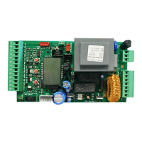
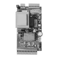
USER 1 - 24V DG
MASTER / SLAVE (CN4)
RADIO MODULE (CNA)
Receiver module connector
JOLLY (CN3)
Connector Programmer Jolly
1
2
3 4
5 6
7 8
9
10
11
12
13
CN1
Start
Stop
24V Aux
(500 mA max)
24V (Flash)
Common
Antenna
START Ped.
Common
Photocell 1
Photocell 2
Common
Flash (-)
Edge
LIGHT (CN5)
Max 100mA
POWER (CN8)
24V~
MOTOR (CN6)
M
Max 200W
CN7
+
-
S
1
2
3
28V Battery charger
Positive battery
Negt e
btey h gr
aiv atr care
NOTE: When using magnetic
limit switches consider the
respective inputs as N.O.
LIMIT SWITCH (CN2)
Limit switch Cl.1 (Yellow)
24V (Red)
Common (White)
Limit switch Op.1 (Green)
1
WARNING: The control unit is designed with the automatic detection of not used
N.C. inputs (photocells, Stop and Limit switch) except the SAFETY EDGE input.
CONNECTIONS
International registered trademark n. 2.777.971
4
67411535 REV 03 - 05/2013