INSTALLATION
MANUAL
SEAKEEPER 3 90378 4 5 of 12
Section 2: ELECTRICAL INSTALLATION
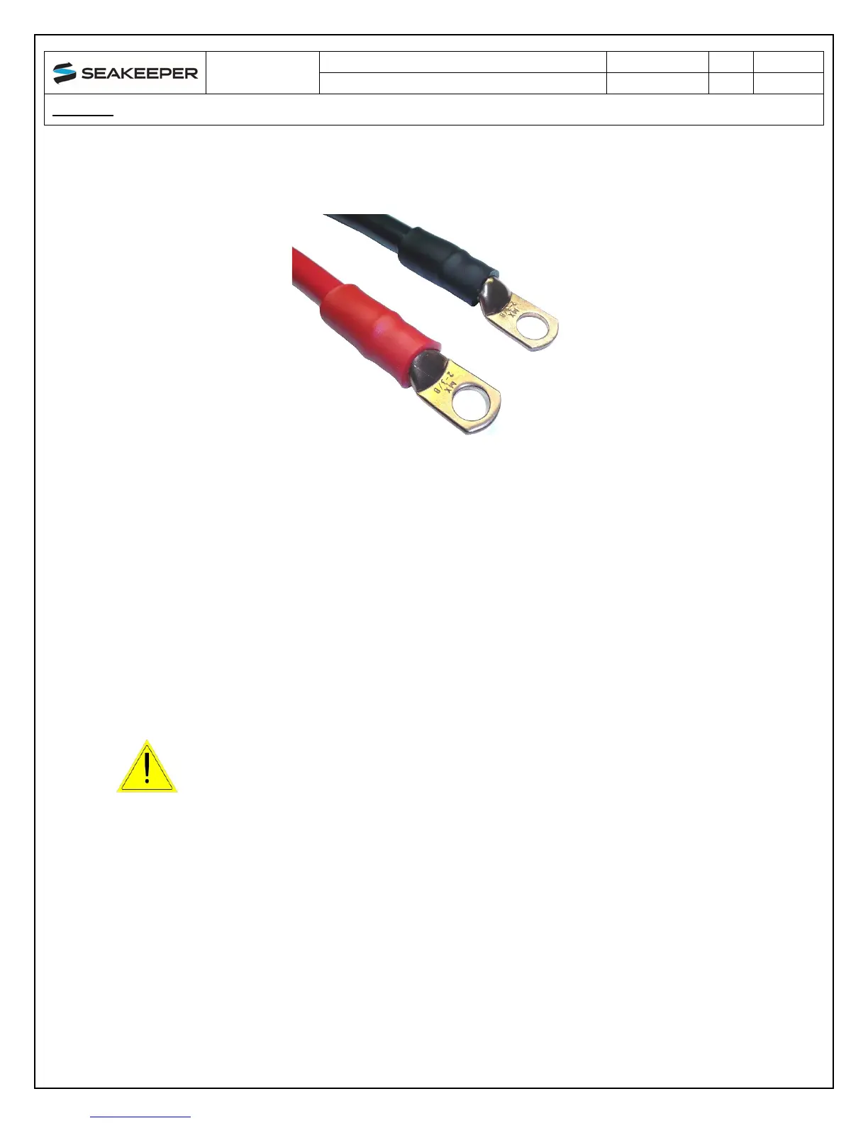
ix. Finally, the heavy-duty eyelet and the end of the conductor insulation should
be sealed with double-wall (adhesive-filled) heat shrink tubing.
FIGURE 5 – TYPICAL 2 AWG CONDUCTOR EYELETS WITH SHRINK TUBING
2. LOW CURRENT 12V POWER INPUT
a. LOW CURRENT 12 VDC POWER SOURCE REQUIREMENTS
i. Source: Battery Bank, 12 VDC, Marine, Deep Cycle
ii. Alternate Source: Power Supply / Battery Charger, 12 VDC
iii. Voltage Range: 10 – 16 VDC
iv. Continuous Current: 9 Amps
v. Overcurrent Protection: 15 Amp (Customer Supplied)
b. LOW CURRENT 12 VDC POWER CONNECTION INSTRUCTIONS
Reversing polarity on the DC power input to the Seakeeper can
result in damaging the electronics in the control system.
i. Install Seakeeper provided DC Power Input Cable, P/N: 20248 as CABLE 7 to
battery bank.
ii. Connect plus conductor (B+, Red) through dedicated over-current protection
device (customer supplied).
iii. Connect minus conductor (B-, Black) directly to battery minus terminal.
iv. Before connecting CABLE 7 to Seakeeper, check for proper voltage and
polarity with a DC multimeter using Figure 6 below.