INSTALLATION
MANUAL
SEAKEEPER 3 90378 4 8 of 12
Section 2: ELECTRICAL INSTALLATION
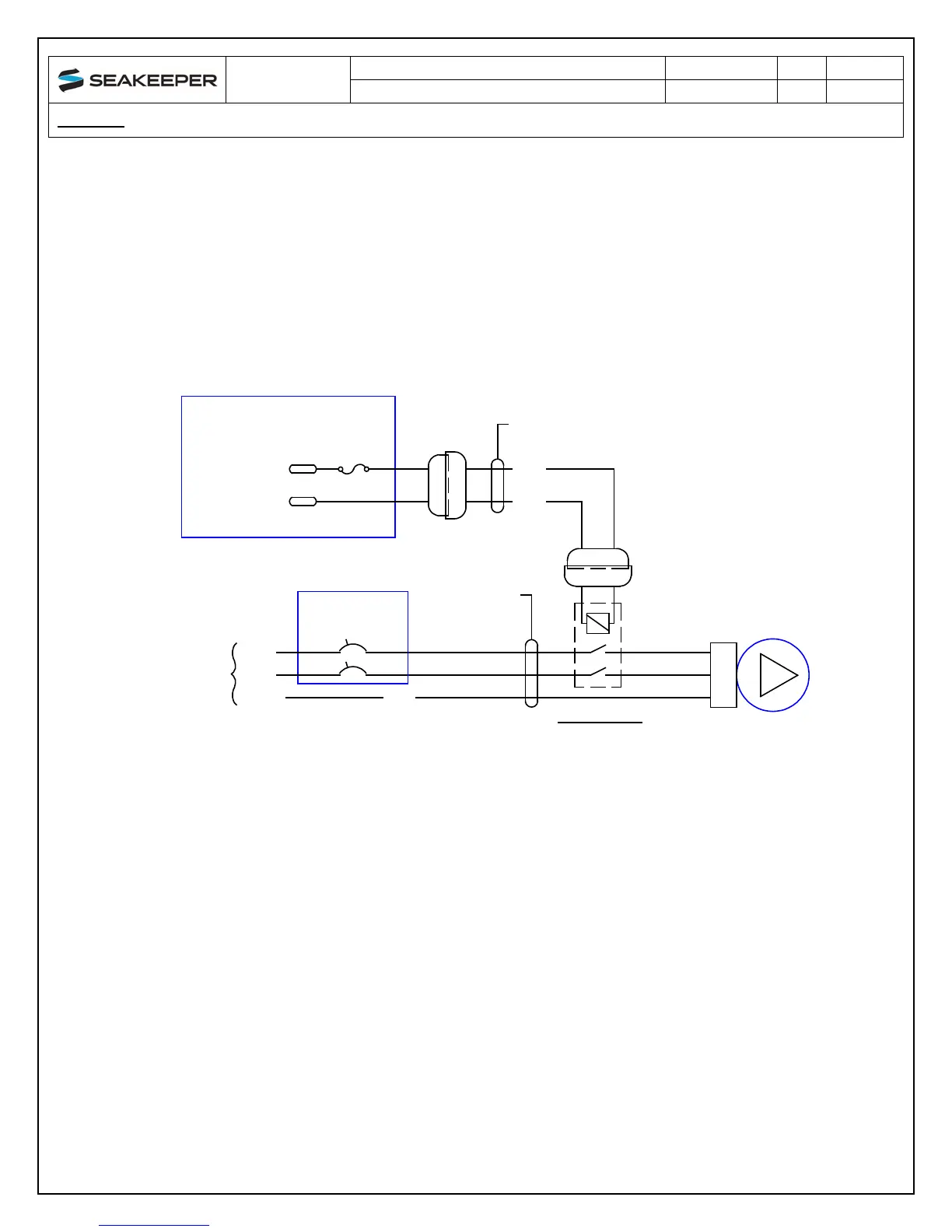
c. SEAWATER PUMP POWER CONNECTION INSTRUCTIONS FOR OTHER
VOLTAGE OR OTHER CURRENT
i. If the customer-supplied Seawater Pump is not rated for 12VDC, 3A or less,
the CABLE 5 output may be used to switch a customer-supplied relay.
ii. Locate CABLE 5 for DC power output to the Seawater Pump from the
Seakeeper.
iii. The recommended wiring is shown in Figure 9. Refer to Figure 7 for Cable 5
wire connections.
FIGURE 9 – RECOMMENDED WIRING FOR SEAWATER PUMPS NOT 12 VDC
OR NOT 3A MAX
ATC FUSE,
3A
SEAWATER PUMP
POWER OUTPUT
12 VDC, 3A MAX
B+
B-
RELAY,
CUSTOMER
SUPPLIED
SEAWATER
PUMP,
CUSTOMER
SUPPLIED
+V
-V
SEAWATER
PUMP
POWER
SEAWATER PUMP
DISCONNECT
SWITCH
-V
EARTH
GRN
CUSTOMER
SUPPLIED
CIRCUIT BREAKER
SEAWATER
PUMP POWER
CABLE,
CUSTOMER
SUPPLIED
CABLE 5
2x16AWG or 2x1.5mm
2
SEAKEEPER SUPPLIED
5m LENGTH
RED
BLACK
SEAKEEPER 3
DEUTSCH
DT06-2S
DEUTSCH
DT04-2P
DEUTSCH
DEUTSCH
2 1
2
1
2
1
2 1
COIL: 12 VDC, < 3A
CONTACTS: FOR SEAWATER
PUMP CURRENT
RELAY SELECTION
+V
PE
DT06-2S
DT04-2P