INSTALLATION
MANUAL
SEAKEEPER 3 90378 4 1 of 15
Section 1: MECHANICAL INSTALLATION
1.0 Introduction
This document is intended to give details and guidance to a boat builder or equipment installer
to install the Seakeeper 3. The Seakeeper 3 is capable of producing loads up to 8.60KN (1,934
lbs.) at each of the four mounts and careful consideration should be given to foundation design
to insure it is capable of transferring these loads into the hull. These loads do NOT include
vessel motion accelerations, such as vertical slam loads which can be high for higher speed
vessels.
There are two methods of installing the Seakeeper 3:
1) Longitudinal Bolt-In Installation
2) Transverse Bolt-In Installation
It is assumed that the installer is familiar with mounting using mechanical fasteners to
marine structures and has performed structural analysis to assure the structure to which
the Seakeeper mounts can properly transfer the loads the Seakeeper creates into the hull
structure. If the installer has any doubt about the ability of the structure to transfer the
loads to the hull then a licensed naval architect or marine engineer should be contacted
to do a structural analysis.
The installer should review the following list of reference drawings to ensure the installation
procedure is fully understood.
Reference Drawings
90388 Seakeeper 3 Hardware Scope of Supply
90374 Seakeeper 3 Installation Details – Bolt in Method
90376 Seakeeper 3 Cooling Water Schematic
90362 Seakeeper 3 Installation Template Kit
90377 Seakeeper 3 Cable Block Diagram
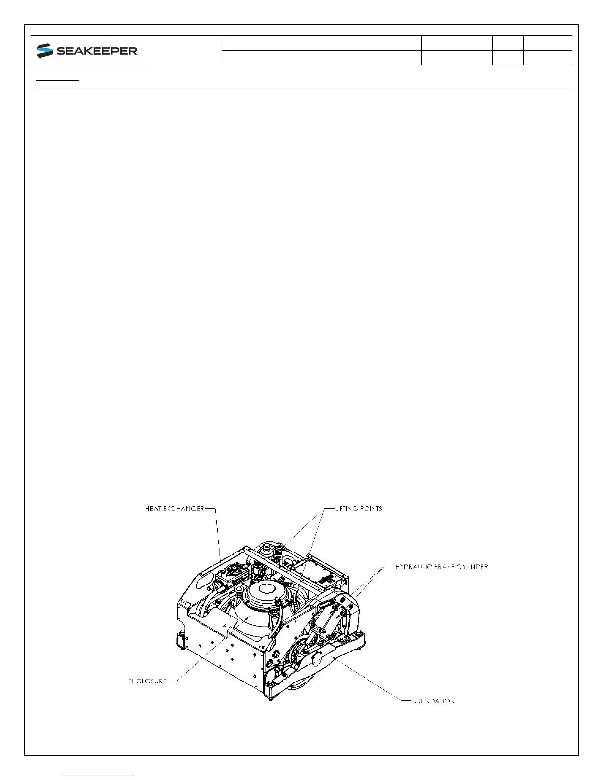
FIGURE 1 – SEAKEEPER 3