INSTALLATION
MANUAL
SEAKEEPER 3 90378 4 3 of 5
Section 3: COOLING INSTALLATION
3.1 Precautions
• Installer is responsible for supplying a dedicated seawater pump and associated
plumbing. Seawater connections on the Seakeeper heat exchanger mate with ¾ inch
(19 mm) hose.
• The seawater output from the Seakeeper powers the seawater pump or central seawater
valve. This pump or valve must operate on 12 VDC and consume less than 3 amps.
Pumps requiring other voltages or higher current can still be controlled by using this
supply from the Seakeeper to trigger an installer-supplied contactor, but a separate
source of power must be provided.
• A self-priming seawater pump (customer/installer supplied) may be required due to
installation location to maintain water flow in all underway conditions where cavitation
near the intake may occur and potentially cause an air-lock condition restricting
seawater flow to the heat exchanger.
• Maximum allowed seawater pressure in heat exchanger is 20 psi (1.4 bar)
• Seawater flow requirement through heat exchanger is 2 GPM (7.6 LPM) minimum
and 6 GPM (22.7 LPM) maximum under all operating conditions of the boat. When
sizing seawater pump, installer should factor in losses for raw water plumbing. In
addition to initial operation at dock, new Seakeeper installations should be checked to be
within the flow requirements while vessel is at speed. Flows higher than 6 GPM (22.7
LPM) could affect heat exchanger life.
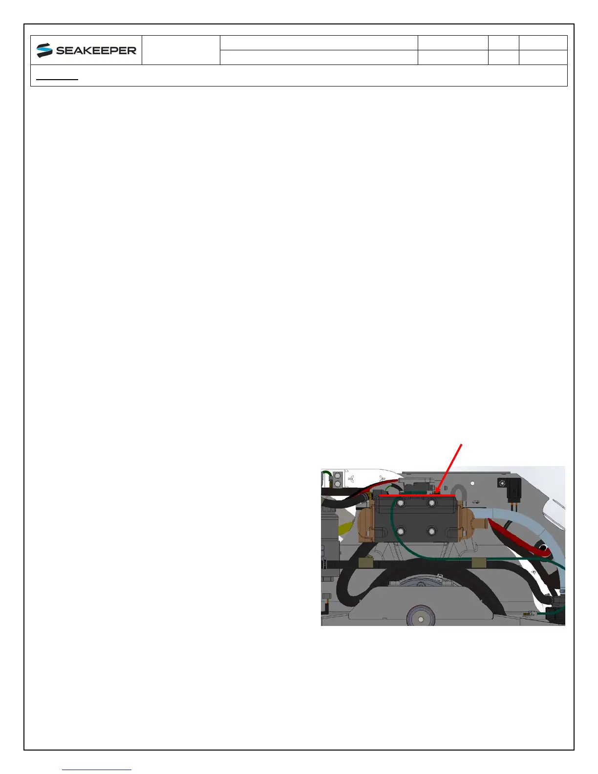
3.2 Adding Coolant
1) Cooling system is filled to proper level
when shipped, with a mixture of 50%
ethylene glycol and 50% distilled water.
Clear tube between thermostat housing
and reservoir should be filled with colored
coolant mixture. If level has dropped,
check for evidence of leaks at all
connections before adding fluid as
described below. If coolant is at the correct
level, skip to seawater connection in
section 3.3.
FIGURE 3 – SEAKEEPER 3 COOLANT LEVEL