3-6
© 2017 SeaStar Solutions i7700 Installation Supplement, Rev. B
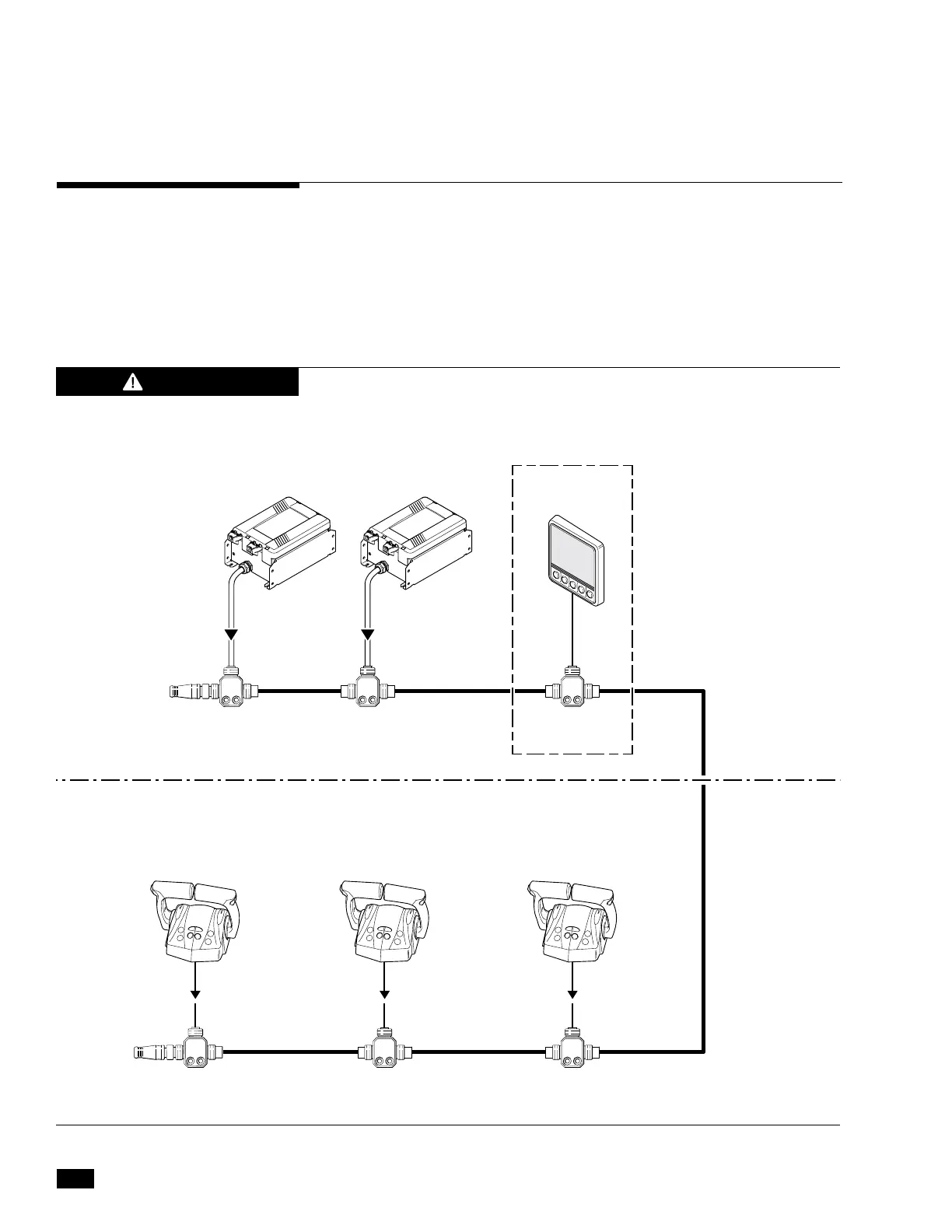
Figure 3-4 and figure 3-5 show the CAN2 network wiring for single
and dual station applications. All tees must be secured using both
screw holes, and the cable drops at each tee must be appropriately
secured and strain-relieved to prevent any pull on the tees. See
figure 3-6 for proper tee installation example.
The CAN2 network must contain two, and only two, terminating
resistors. One terminator should be installed at each end of the
network backbone.
3.5 CAN2 Harness Connections
FAILURE TO SECURE HARNESS MAY RESULT IN HARNESS WEAR,
CAUSING LOSS OF THROTTLE CONTROL, PROPERTY DAMAGE,
PERSONAL INJURY AND/OR DEATH.
WARNING
Figure 3-4. CAN2 wiring diagram, triple station, twin engine.
SHIFT/THROTTLE ACTUATORS
2 x NETWORK TEES CM10060
3' PIGTAIL3' PIGTAIL
3' PIGTAIL
CM20029
CM100XX
(Where XX is the length in feet required.
6', 12' and 20' lengths are included in the kit.)
MALE
TERMINATOR
CM10051
FEMALE
TERMINATOR
CM10052
CM10060CM10060CM10060
TEMPORARILY
INSTALLED
3' PIGTAIL
MAIN STATION
CONTROL HEAD
OPTIONAL
SECOND STATION
CONTROL HEAD
OPTIONAL
THIRD STATION
CONTROL HEAD
3' PIGTAIL
CANtrak SETUP
TOOL EPSK1207
HATCH OR CONSOLE
MOUNTED COMPONENTS
DASH MOUNTED
COMPONENTS

 Loading...