3-9
© 2017 SeaStar Solutions i7700 Installation Supplement, Rev. B
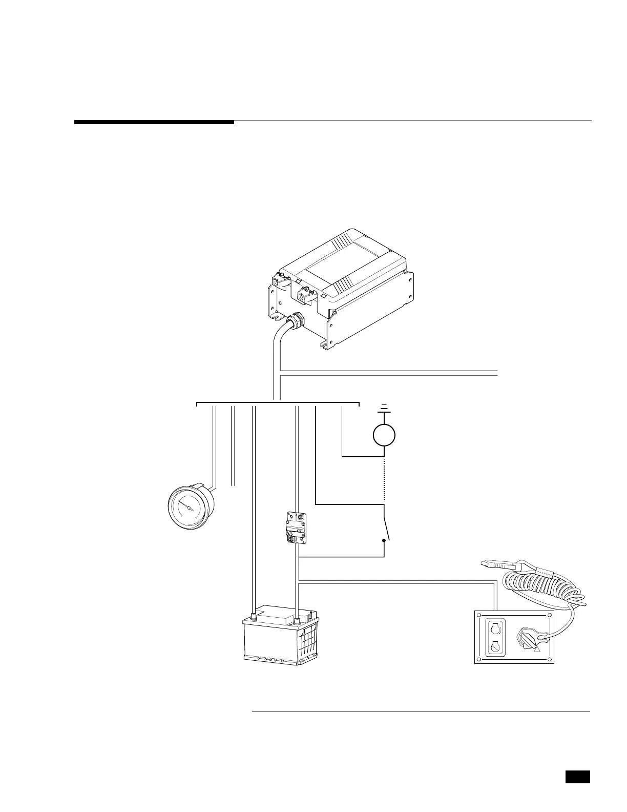
The actuator harness contains a gray lead that can be connected to an
analog engine tachometer. You will not need to make this connection
if you are getting the speed source through an NMEA2000 network, or
if you have made an analog tachometer connection on the PCM CAN2
harness. See section 6.5 in Book 50 for more information on engine
speed source selection and wiring.
3.6 Analog Tachometer
Figure 3-8. Actuator harness wiring schematic.
RUN
OFF
BREAKER
CAN 1
(
NOT USED
)
STARTER SOLENOID
GY
GY – Gray
BK – Black
RD – Red
YL – Yellow
VT – Violet
BK RD YL YL/RD
ORIGINAL START CIRCUIT
CAN2 NETWORK
ENGINE START
ENGINE
ANOLOG
TACH.
IGNITION
KEY SWITCH
PANEL
POWER SOURCE
ACTUATOR
+–
 Loading...