EasyManua.ls Logo

Seatex DPS 132 User Manual

Default Icon
108 pages
To Next Page IconTo Next Page
Page #1 background imageLoading...
Page #1 background image
Seatex DPS 132
Installation Manual
Issued: 2004-07-01
FSP ref.: A11211400XRBRA0

Table of Contents

Question and Answer IconNeed help?

Do you have a question about the Seatex DPS 132 and is the answer not in the manual?

Seatex DPS 132 Specifications

General IconGeneral
BrandSeatex
ModelDPS 132
CategoryMarine GPS System
LanguageEnglish

Summary

Seatex DPS 132 Installation Manual

Notice

Copyright and Contact Information

Contains copyright and company contact details.

Revision Log

Revision History Table

Details document revisions, dates, and reasons for changes.

1. Introduction

1.1 About this manual

Explains the manual's content and intended audience.

Safety and Operational Notes

Highlights important safety warnings and user notes for equipment operation.

1.2 References

1.3 Abbreviations and Acronyms

2. Specifications

2.1 Physical Dimensions

Provides measurements for the DPS 132 unit, cabinets, and antennas.

2.2 Power Requirements

Specifies voltage, power consumption, and battery considerations.

2.3 Environmental Specification

2.4 Radio Frequencies

2.5 Cable Specification

2.6 Compass Safe Distance

3. Installation

3.1 System Components

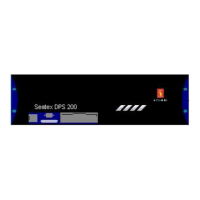
Lists the standard parts included in a typical DPS 132 system delivery.

3.2 Logistics and Safety

3.3 Location of System Parts

3.3.1 DPS 132 Unit Placement

Guidance on indoor installation requirements for the DPS 132 unit.

3.3.2 Antenna Placement

3.4 DPS 132 Cabinet Mounting

Cabinet Grounding Caution

Emphasizes the critical need to connect the cabinet to a grounded outlet.

3.5 Coax Connector Installation

3.6 Antenna and Cable Mounting

3.6.1 GPS Antenna and Cable Mounting

Specific steps for installing the GPS antenna and its associated cable.

GPS Cable Caution

Warns against short-circuiting the GPS antenna cable when the unit is powered on.

3.6.2 IALA Beacon Antenna and Cable Mounting

IALA Beacon Cable Caution

Warns against short-circuiting the IALA beacon antenna cable during installation.

3.7 External Input/Output Serial Lines

3.7.1 Connectors

Details the rear panel connectors for communication interfaces.

3.7.2 Serial Lines Configuration

Serial Line Pin Layouts

3.7.3 PPS Signal

3.7.4 Connecting Procedure

3.8 Starting the System

3.8.1 Configuring COM Ports

Guide to reconfiguring COM port settings using the registry.

3.9 Editing Setup File

Setup File Parameters

Lists the various parameters that can be configured in the setup file.

3.9.1 Selecting Target

3.9.2 Datum Selection

3.9.3 Output Telegrams

ABBDP Telegram Format

Details the ABBDP message structure, fields, and data types.

ARABB Telegram Format

DPGGA Telegram Format

GGA Telegram Format

GGA_1.5 Telegram Format

GGA_MAG Telegram Format

GGA_CEG Telegram Format

GLL Telegram Format

GLL_1.5 Telegram Format

GLL_2.0 Telegram Format

GNS Telegram Format

GSA Telegram Format

GST Telegram Format

GSV Telegram Format

PSXN_23 Telegram Format

VBW Telegram Format

VTG Telegram Format

Westerstrand Messages

ZDA Telegram Format

3.9.4 Time and Position Precision

3.9.5 Output Mode and Interval

3.9.6 UTM Mode and Zone

3.9.7 Satellite and Fix Computation Settings

3.9.8 Height Aiding

3.9.9 Range and Age Limit for Reference Stations

3.9.10 SBAS Configuration

3.9.11 Differential Correction Settings

3.9.12 Handling of Corrections

3.9.13 Offsets in Reference Station Co-ordinates

3.9.14 Gyro Interface

3.9.15 Vessel Information

3.9.16 Offset Vectors (Lever Arms)

3.10 Reference Stations

3.11 Commissioning

4. Installation Drawings

4.1 Physical Description of DPS 6U Cabinet

Technical drawing showing the physical dimensions and layout of the DPS 6U cabinet.

4.2 Physical Description of DPS 12U Cabinet

Technical drawing showing the physical dimensions and layout of the DPS 12U cabinet.

4.3 GPS Antenna

Diagram illustrating the GPS L1/L2 antenna and its connector.

4.4 GPS Antenna Mounting Specification

Drawing detailing the recommended mounting procedure and specifications for the GPS antenna.

Appendix A - IALA Beacon Antenna

Appendix B - 1/2" Coax Cable Specifications

Appendix C - RG-213 Specifications

Appendix D - DPS Setup File

Appendix E - Reference Station Default File

Appendix F - External Remote Cabinet

Appendix G - Mounting without DPS 132 Cabinet

Appendix H - NMEA Display

Appendix I - Optional IALA Beacon Antenna

Appendix J - RG-214 Specifications

Appendix K - DGPS 465

Related product manuals