Seatex DPS 132 Installation Manual, rev. 0 Installation
16
3.7 External input and output serial lines
3.7.1 Connectors
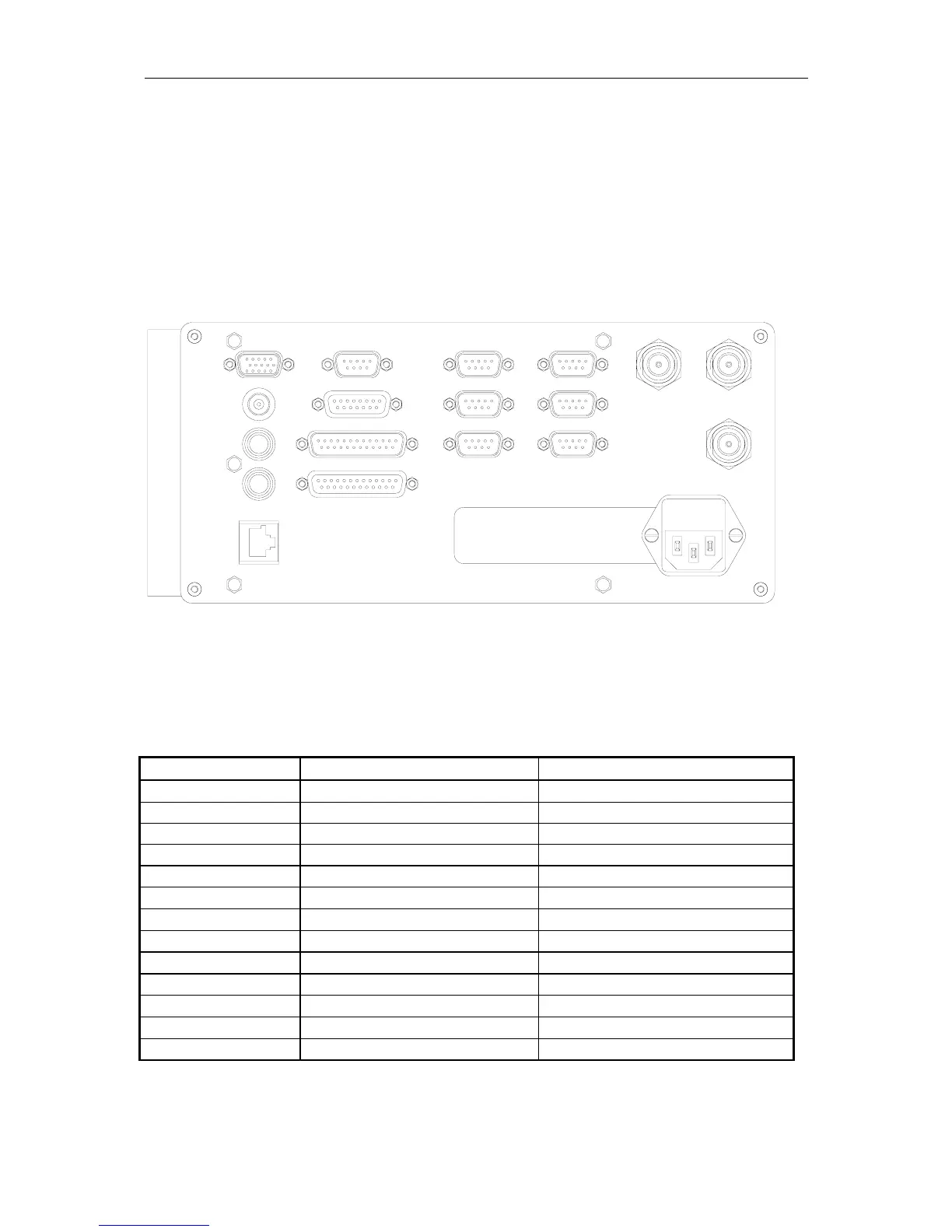
The rear panel of the DPS 132 unit contains communication interface ports for interfacing to
external systems.
Figure 1 Rear view of the DPS 132 unit
The use of the different connectors:
Connector Type Connected To
VGA Video display unit
PPS BNC-Connector Not in use
Mouse PS/2 Mouse
Keyboard PS/2 Keyboard
Net Ethernet output Not in use
Com2 - Com10 9 pin Dsub male User configurable
MRU (Com12) 15 pin Dsub female User configurable
LPT1 25 pin Dsub female Not in use
Aux-Serial 25 pin Dsub male Not in use (user configurable)
GPS Ant1 N-Connector 50 Ohm female GPS antenna
GPS Ant2 N-Connector 50 Ohm female Not in use
IALA Ant3 N-Connector 50 Ohm female IALA antenna
100-240 V AC Power Input of 110/220 V AC
Table 1 Connectors
Fuse : 2A
Input : 100-240VAC/47-63Hz/100VA
NET
KEYB
MOUSE
PPS
VGA
COM9
COM6
MRU
AUX - SERIAL
LPT1
grounded outlet only
Class1: Must be connected to
COM7
COM10
COM2
COM5
COM8
IALA
ANT3
GPS
ANT1
GPS
ANT2