Seatex DPS 132 Installation Manual, rev. 0 Installation
18
Com 1, Com2, Com 4 and Com14 through Com18 (the Aux-serial port) are not
galvanically isolated. These ports should only be used internally.
Note All external cables connected to the DPS 132 system must be screened and
connected to ground in both ends. "Pigtail" connections must be avoided.
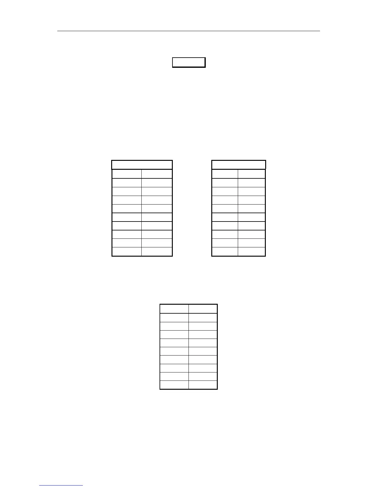
The panel connectors for Com1, Com2 and Com5 to Com10 are DB-9 male. Pin layout is
described below:
RS-232
RS-422
Pin no. Signal Pin no. Signal
1 N/C 1 N/C
2 RXD 2 RX+
3 TXD 3 TX+
4 N/C 4 N/C
5 REF 5 REF
6 N/C 6 N/C
7 RTS 7 TX-
8 CTS 8 RX-
9 N/C 9 N/C
Table 3 Pin layout for Com5 to Com10
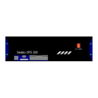
The panel connector for the MRU port is DB-15 female. Pin layout is described below:
Pin no. Signal
1
7 PGND
14 +24V
2 TX+
9 TX-
3 RX+
10 RX-
11 XIN
5 LGND
Table 4 Pin layout for MRU port
CAUTION