Seatex DPS 132 Installation Manual, rev. 0 Appendix F – External remote cabinet
72
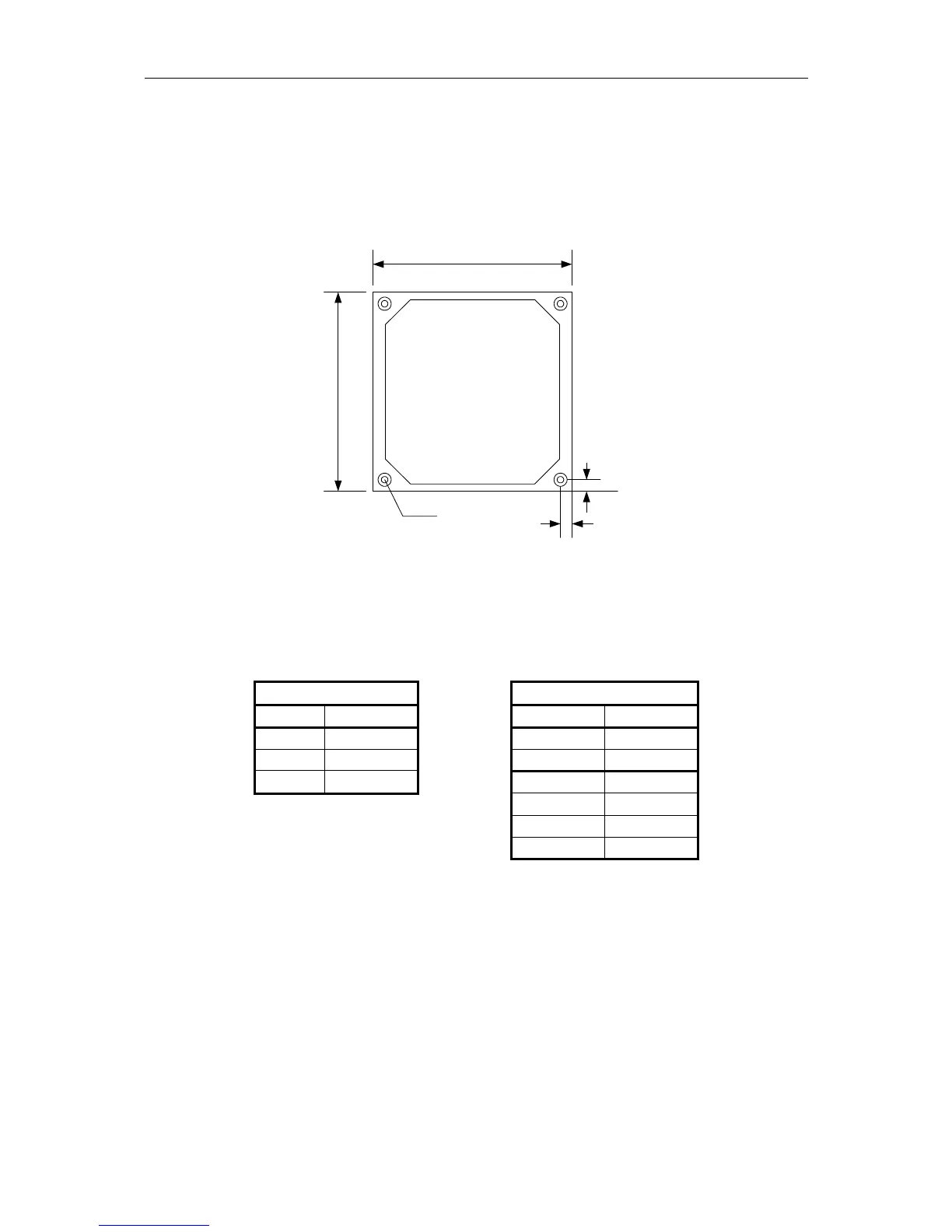
Mechanical Installation
Mount the cabinet by fastening the four screws at the bottom of the cabinet. The screw holes
stand out 3 mm to permit air circulation behind the cabinet.
Figure 8 Cabinet dimensions
Electrical Installation
Power Data Input/output
X1 Signal X2 Signal
1 230 V AC 4 TX-
2 230 V AC 5 TX+
3 GND 6 RX-
7 RX+
8 PPS-
9 PPS+
Table 28 Cable terminal strip table
Note It is not necessary to connect PPS- and PPS+ to the DPS unit.
Ø 8.5
400 mm
400 mm
35 mm
35 mm