www.selbit.pl
- 10 -
UP. Analogically it is important to check this connections and create a proper working.
Otherwise it may cause incorrect controller’s operating.
If above checking instructions are correct please follow next step – controller's starting
CHAPTER 3
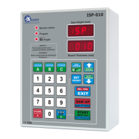
Controller’s parameters checking
To use those instructions it is required to check pitch of the feeding screw. Please measure it
and write it down below:
Pitch screw in this machine is ……………. Mm
Next, please check type of the encoder mounted on this machine at the end of the screw
(photo 4a). Encoder’s type is marked on its casing and shows impulses to rotation ratio
generating. Please note this number below:
Encoder’s impulses to rotation ratio mounted on this machine is ………… imp/rot.
Next, using table 1 from point 4 of this instruction check which divider is correct for this
sawing frame machine. Example: for pitch screw 7 mm and encoder’s impulses to rotation
ratio 42 imp/rot. divider read from the table is 12.
After checking this values please note it below:
Divider (table 1) …………………
If the controller is mounted on the chain sawing frame machine thus divider according
to the table 1 is 5.
For checking all controller’s parameters, please follow points 1…5 below.
1- Input divider checking
For checking input divider value please turn on the controller and during the ISP 010 is
displayed please press “Clibr.” button. The controller display in “Board Thickness” window
divider symbol at the left side and its value at the right one. Please compare read value with
value which should be provided from the table 1. If the value is not correct, please type in
required one and save it to the controller’s memory pressing “Start/Next Cut” button. Text
“Save” should be shown.