www.selbit.pl
- 4 -
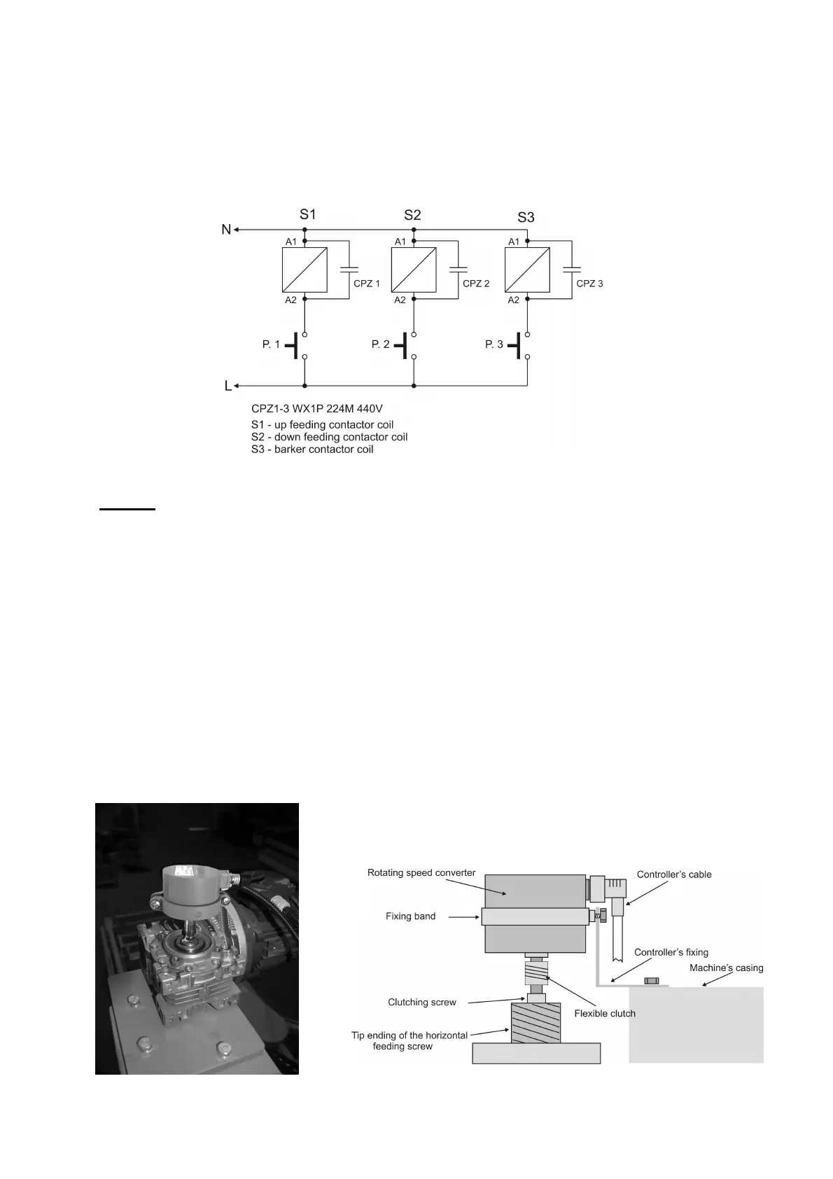
Those CPZ outputs should connected in parallel to the contactors’ coil. CPZ should be
connected with contactor’s coil of the down feeding, up feeding and barker contactor
separately (if the sawing frame machine is equipped with barker).
Fig. 3 Choke CPZ constructions and connections
Point -4
Rotating encoder mounting
Added rotating encoder is designed to convert rotation of the head saw feeding screw for
electrical impulses. Number of the impulses depends on screw pitch and this relation
describes table 1. In most of the frame sawing machines this screw has got free tip where the
encoder can be installed. Please make a concentric hole in the screw and mount encoder’s
clutch. Please make sure that this hole is concentric otherwise it can cause swinging and
eventually incorrect encoder working and its damage. Please make hole around 15 mm and
create thread M8. Next mount encoder using fixing band (fig.4). The band should be attached
to the special fixing which because of the variety of the frame sawing machines should be
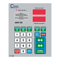
created individually. Example of the encoder mounting is shown at the photo 4a below.
Photo 4a. Example of the necoder mounting. Fig. 4 Encoder mounting ex ample.